
Reducing the temperature in the seal chamber offers many benefits to the performance and reliability of a mechanical seal operating in hot service. This is one of the most effective ways to increase the vapor pressure margin and prevent the pumped fluid from flashing in the seal chamber or at the interface of the mechanical seal’s faces. Additionally, lowering the seal chamber temperature also increases the fluid’s viscosity, providing a more stable fluid film at the interface of the seal faces. One method of achieving a reduction in temperature is to circulate fluid from the seal chamber through a heat exchanger and return the cooled fluid back into the seal chamber. The heat exchanger is often referred to as a “seal cooler” since it is not part of the process, but just an auxiliary system component. This piping arrangement is known as an API Plan 23. When installed, operated and maintained correctly, a Plan 23 is one of the most effective methods of lowering the seal chamber temperature.
Creating Flow
Fluid is circulated through the heat exchanger by a pumping ring incorporated into the mechanical seal’s design. The pumping ring, typically a slotted wheel or helical scroll, is spinning with the pump shaft and functions as a miniature pump within the seal chamber. In comparison to the main impeller on the pump shaft, the pumping ring only generates an extremely small fraction of pressure head and flow. Thus, it is of critical importance that the design, selection and installation of the flow circuit is optimized to provide the least resistance to flow, thereby maximizing the circulation rate and the ability of heat energy to be transferred from the seal chamber to the heat exchanger.Optimizing the Flow Circuit
There are three main elements to the flow circuit that can be optimized:- The heat exchanger
- The interconnecting tubing between the heat exchanger and seal chamber
- The entry and exit ports in the seal chamber (or mechanical seal) and their position relative to the pumping ring
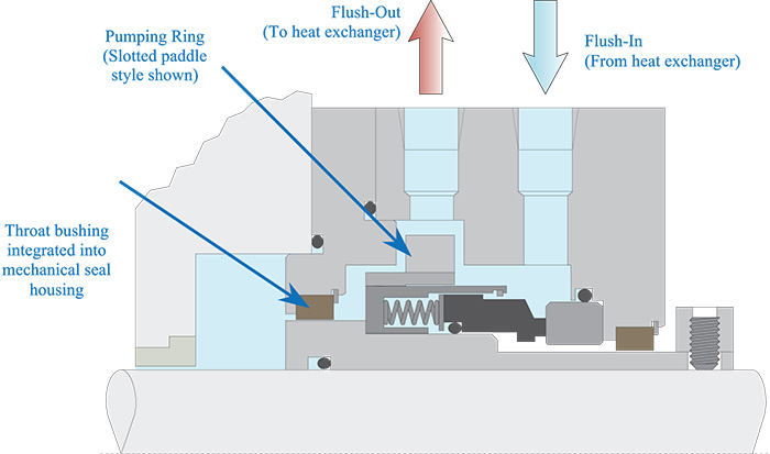 Figure 1. Typical mechanical seal with integrated pumping ring and throat bushing (Courtesy of FSA)
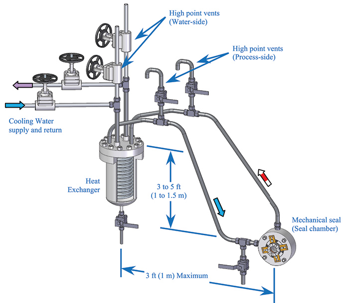 Figure 2. Typical API Plan 23 arrangement
Installation & Commissioning
The heat exchanger should be mounted in a position above and to the side of the mechanical seal so that short direct tubing runs can be made to connect the seal chamber (or mechanical seal) flush ports to the heat exchanger. Mounting the heat exchanger at or near the maximum height noted in Figure 2 can enhance thermosyphoning (flow induced by the small difference in density of the hot fluid entering the heat exchanger and cool fluid exiting). This can assist the flow from the pumping ring while the pump is operating and continue to create flow while the pump is idle. The interconnecting tubing between the seal chamber (or mechanical seal) flush ports and the heat exchanger should slope upwards towards a high point vent at a minimum slope of 0.5 inches per foot (40 millimeters per meter). As the interconnecting tubing will be hot during operation, the potential for contact burn injuries to maintenance and operation personnel is present. Expanded mesh heat guards are the preferred method of mitigating burn hazards since they allow natural heat convection to occur from the exposed tubing. For installations where space is tight, mechanical insulation can be used to mitigate the hazards. The orientation of the heat exchanger should be selected so that any air trapped in the cooling coils can naturally flow to a high point and be vented. The location and height of the heat exchanger should be selected so that it facilitates access for servicing the heat exchanger while minimizing the impact of access to the pump for maintenance. The heat exchanger should never be mounted directly over the pump or motor. Prior to starting the pump, the process and water side of the heat exchanger need to be vented of any trapped air or vapor. High point vents fitted to both the cooling water and process piping facilitate the venting. Venting of the process side also vents the heat exchanger, the seal chamber and the interconnecting tubing. Process side venting often requires special sizing and routing considerations depending on fluid properties, system pressure, temperature and hazards. The design must ensure effective venting capability while maintaining safe operation.Maintenance
Cleaning the heat exchanger should be performed when loss of efficiency is apparent. Normally, this results from fouling of the cooling water side of the heat exchanger. The rate at which fouling occurs depends on the quality of the cooling water and the heat load placed on the heat exchanger. Areas with hard water will require frequent cleaning of the heat exchanger to remove mineral scale. The heat exchanger should be cleaned at every seal change.Additional Considerations
There are some applications where this solution may not be the ideal choice:- Dirty fluids can result in accumulation of solids in the seal chamber that interfere with operation.
- Fluids with gaseous constituents can cause the Plan 23 circuit to vapor lock and prevent flow through the heat exchanger.
- Waxy fluids or fluids that solidify at ambient or cooling water temperatures can solidify in the heat exchanger while the pump is idle.
- Fluids with high viscosities may not be able to be pumped through the Plan 23 circuit at a sufficient flow rate to transfer the heat load placed on the system.
