
Protect your system from this damaging phenomenon.
09/18/2017
Editor’s Note: This article originally appeared as a two-part series in the August and September 2008 issues of Pumps & Systems.
Water hammer (also waterhammer) is a pressure surge that can arise in any pumping system that undergoes an abrupt change in its rate of flow and usually results from pump starts and stops, the opening and closing of valves, or water column separation and closure. These abrupt changes can cause all or part of the flowing water column to undergo a momentum change. This can produce a shock wave that travels back and forth between the barrier that created it and a secondary barrier. If the intensity of the shock wave is high, physical damage to the system can occur. Oddly enough, it can be more of a concern in low pressure applications.
Water hammer is yet another example of conservation of energy and results from the conversion of velocity energy into pressure energy. Since liquids have a low compressibility, the resulting pressure energy tends to be high.
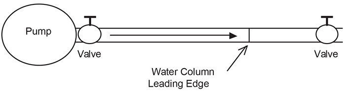 Figure 1. Example system (Courtesy of the author)
Why
It is water’s (and dissolved air’s)compressibility that causes water to act differently than the metal column. Were it not compressible, its leading edge would be permanently crushed or the entire column would bounce backward. When the leading edge of a water column strikes the closed valve, it abruptly stops. Since the water behind the leading edge is still in motion, it begins to compress. This allows a small amount of water to continue to flow into the pipe even though the leading edge has halted. When flow ceases, all of its kinetic energy of motion and that due to compression is converted into pressure energy. Compression begins at the leading edge of the water column, and since the additional energy it produces cannot continue past the closed valve, a pressure or shock wave is generated and travels along the path of least resistance, which, in this example, is back upstream. Its inception is similar to the echo produced when a sound wave, traveling through air, strikes a similar barrier. When the wave hits the upstream valve, it is reflected back downstream but with a diminished intensity. This back and forth motion continues until friction and reflection losses cause the wave to disappear. The speed at which a wave travels and the energy it loses during travel depends on the density and compressibility of the medium in which it travels. The density and compressibility of water make it a good medium for shock wave generation and transmission. The pressure waves created by hydraulic shock have characteristics similar to those of sound waves and travel at a similar velocity. The time required for a water hammer pressure wave to negotiate a length of pipe is simply the pipe length divided by the speed of sound in water (approximately 4,860 feet per second [ft/sec]). In water hammer analysis, a time constant that is often used describes the progression of the wave from its inception to the secondary barrier and then back again. It takes the form of Tc = 2L/a (where L is the pipe length and a is the velocity of the wave, which is the speed of sound). In a 1,000 foot pipe, the wave can make a complete round trip in less than one half second.P(additional) = aV / 2.31g Equation 1 P = the additional pressure the shock wave creates a = wave velocity V = the velocity of the flowing water in the pipe in feet per second g = the universal gravitational constant 32 ft/sec2 2.31= the pressure conversion constant.
The pressure created by this shock wave is directly proportional to both the wave velocity and the velocity of the water flowing in the pipe. Although Equation 1 does not take into account the effect of pipe length, diameter and elasticity, it will provide some insight as to the additional pressure created by a water hammer pressure wave. At a pipeline velocity of 5 ft/sec, the additional pressure created by the shock wave is approximately 328 psi. Increasing that velocity to 10 ft/sec increases the additional pressure to about 657 psi. Obviously, systems that are not designed to accommodate such an increased pressure are often damaged or even destroyed.
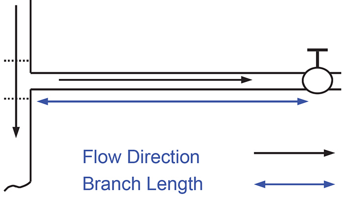 Figure 2. Main pipeline with a branch circuit
Valve Closure & Opening
One of the primary causes of water hammer is the abrupt closure of a valve. Figure 2 shows a main pipeline with a branch circuit that is fed by a “Tee.” At the end of the branch is a valve. The black arrows show the flow direction in the primary and branch lines, and the purple arrow is the length of the branch line. As in the system in Figure 1, the valve acts as the primary barrier, but this time the secondary barrier is the “Tee.” If water is flowing in the branch line and the valve is closed quickly, a shock wave will develop. Its inception follows the same sequence of events in our hypothetical example. One small difference is that some of the intensity of the waves will be lost in the “Tee” as it is open to the main pipeline on either side. Still, a significant portion will be reflected back toward the valve.P = 0.07 (VL / t) Equation 2 P = the additional pressure generated by the shock wave V = the flow velocity in ft/sec L = the pipe length between the barriers in feet t = the valve closing time in seconds. 0.07 = a derived constant.
A difference in this example is that we have some control over the valve closure time. In our hypothetical example the valves closed at nearly the speed of light. Closure time has a significant effect on the inception and intensity of water hammer. Two other variables, flow velocity and pipeline length, are also major factors. Equation 2 shows the relationship of these three variables. The additional pressure created by the shock wave is directly proportional to flow velocity and pipeline length and inversely proportional to closure time. In other words, higher values of V or L will increase pressure while higher values of t will result in a decreased pressure. Table 1 shows the results from this equation when using differing velocities, pipe lengths and closure times. The V values are 5 and 10 ft/sec, L values are 100 and 1,000 feet, and t values are 1 and 2 seconds. Two of the variables are constant in each example.
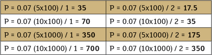 Table 1. Additional pressure generated by different velocities, pipe lengths and closure times
Pump Starts & Stops
Water hammer’s effects can be more significant in low pressure systems. The additional pressure generated by a shock wave is proportional to the length of the pipe and velocity of the water flowing in it and is completely independent of its operating pressure. Therefore, the shock wave created in a 1,000 foot pipe flowing at 5 ft/sec will be the same whether the operating pressure is 50 psi or 200 psi. The difference is the ratio of shock pressure to design pressure can be significantly higher in the low pressure system, therefore the potential for damage is greater. In many large systems, it is normal procedure to start a pump against a closed discharge valve. Once the pump is running at full speed, the valve is opened slowly. Flow is initiated and then increases to its maximum as the valve continues to open. This procedure is reversed when a pump is stopped. Starting and stopping against a valve that is opened or closed slowly will inhibit the initiation of water hammer. The discharge valve may be operated manually or by some automatic mechanism. One shortcoming of manually operated valves occurs during a power outage. When a pump motor loses power, the reduction in pump speed and flow occurs rapidly. The resulting change of kinetic energy to that of pressure can produce water hammer waves in the discharge line. As the water column reverses direction, the impeller will accelerate backward. When it reaches its maximum reverse speed, backward flow is reduced and an additional pressure surge is created. In most pressure boost applications, a “spring loaded” check valve is installed at or near the pump discharge and remains closed when the pump is idle. When the pump starts, flow does not begin until the pressure it generates exceeds the pressure on the downstream side of the closed valve. If the downstream pressure is not allowed to decrease below a certain level, flow increases slowly and water hammer inception is avoided or reduced. When the pump stops, an unexpected event occurs—a quick closing valve actually inhibits, rather than initiates, water hammer. In this particular instance, the spring provides quick closure of the valve, which prevents the water column from changing direction due to the higher downstream pressure. Even though flow changes abruptly, pressure remains relatively constant throughout the downstream column. If a standard check valve was installed, the water column would accelerate backward, slam the check closed and initiate a shock wave. Today, variable frequency drive (VFD) control is used in many applications to eliminate the inception of water hammer during pump starts and stops. This technique, known as soft start and stop, is accomplished by ramping the motor speed up or down over a period of seconds. This allows the flow velocity to increase or decrease much more slowly than it would during across the line starts and stops. So far, our discussion of water hammer has dealt with single phase systems. In these systems, water remains in a single state (liquid in our examples) regardless of the changes in the hydraulic conditions. The shock waves generated by single phase systems are due to an abrupt change in flow and the resulting transformation of kinetic energy. The water hammer generated by water column separation and closure is a two phase process. In a two phase system, water changes state and can exist both as a liquid and a vapor within the same confined volume. This change can take place whenever the pressure in a pipeline is reduced to that of the vapor pressure of the water. When a pressure drop occurs, the water column can become separated, in one or more locations, by a pocket of water vapor. When the pressure rises above the vapor pressure, the column rejoins or closes and can create a high pressure wave. Water column separation, by itself, can cause problems in very large diameter or thin wall pipes (which can collapse), but water hammer during closure is the more common problem. Water column separation can occur when a pump is stopped and the water column reverses direction or in condensate lines where high temperatures can mitigate the need for a large pressure drop. Although both forms can be extremely damaging, condensate lines tend to be far more dangerous. The shock waves generated by column closure can travel in opposite directions, and if they hit secondary barriers they can be redirected back toward one another. It would not be unusual for these reflected waves to increase in intensity when they collide. This is certainly the case with water and voltage waves and may account for the often greater damage resulting from closure-initiated water hammer.
In the coming months, we will publish articles that fill a gap in our industry: basic information for new pump users. We’ll pull these from classic Pumps & Systems articles, as well as new content. If you have a go-to article for training new employees or refreshing yourself on the basics, please tell us about it at pumpeditors@cahabamedia.com.
