
Understanding the equipment’s operation capabilities and how to calculate the required size is critical.
04/03/2015
Last of Three Parts Read Part 1 here. Read Part 2 here. In circuits that require cleaning at the end of each process, pulsation dampeners pose an added challenge. Every pulsation dampener has hard-to-reach internal corners that are difficult to clean. One solution is to use a quick dismantling system to extract the bladder out of the dampener, then clean the bladder and the interior of the dampener body separately. If dismantling the bladder is impractical, users can increase the pressure of the cleaning liquid to be higher than the pumping pressure of the process product. This will cause the internal corners between the bladder or membrane and the inner surface of the dampener to expand, allowing a better access to the cleaning fluid.
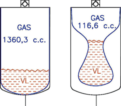 Figure 1. Pulsation dampeners using bladders require special considerations. (Courtesy of HIDRACAR, S.A.)
Circuits with a Variable Working Pressure
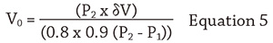
Circuits that have variable working pressures require different solutions. Consider a circuit that must work at an initial pressure of 20 bar and a final pressure of 200 bar, with the amount of liquid flowing through the dampener in each alternating cycle of the pump (δV) equaling 15 cubic centimeters (cc). The maximum residual pulsation is accepted at 200 bar of +/- 5 percent. At 20 bar, the residual pulsation will be much lower because the dampener size is calculated for the maximum circuit pressure. So when the circuit is working at the minimum pressure, the gas inside the dampener will expand. Consequently, the residual pulsation will decrease from the +/- 5 percent initially admitted. The pump is a single-piston type, and its capacity per stroke is 30 cc. Equation 1 can be used to calculate the necessary volume of a pulsation dampener. P2 x V2 = P0 x V0 Equation 1 Where: P2 = maximum pressure value accepted in the circuit V2 = final gas volume P0 = inflating gas pressure of the dampener V0 = volume of the dampener In the example system, P0 = 0.9 x 20 = 18 bar Equation 2 P2 = 200 + 5% = 210 bar Equation 3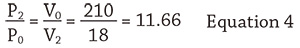 Equation 5 can calculate the volume of a dampener for the maximum pressure of 210 bar.
 This volume is equivalent to V2, and consequently:
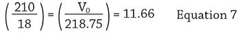 and
V0 = 218.75 x 11.66 = 2,550.62 cc Equation 8
Theoretically, this is the total dampener volume necessary for this application. However, the ratio of V0 / V2 cannot be higher than four in bladder type dampeners to prevent the bladder from wrinkling excessively, which could tear it prematurely. In the example, the ratio is 2,550.62 / 218.75 = 11.65, nearly three times higher than the recommended value of four.
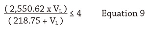
To avoid exceeding this ratio, liquid must be introduced into the bladder with the gas. This is usually the same liquid moving through the circuit, but any liquid that will not react with the bladder material or the circuit liquid can serve this purpose. In the example, this volume of liquid that must be introduced into the bladder (VL) is calculated using Equation 9:
and
V0 = 218.75 x 11.66 = 2,550.62 cc Equation 8
Theoretically, this is the total dampener volume necessary for this application. However, the ratio of V0 / V2 cannot be higher than four in bladder type dampeners to prevent the bladder from wrinkling excessively, which could tear it prematurely. In the example, the ratio is 2,550.62 / 218.75 = 11.65, nearly three times higher than the recommended value of four.
To avoid exceeding this ratio, liquid must be introduced into the bladder with the gas. This is usually the same liquid moving through the circuit, but any liquid that will not react with the bladder material or the circuit liquid can serve this purpose. In the example, this volume of liquid that must be introduced into the bladder (VL) is calculated using Equation 9:
 When this system is operating VL = 558.54 cc
The total dampener volume needed will be
2,550.62 + 558.54 = 3,109.16 cc
When this system is operating VL = 558.54 cc
The total dampener volume needed will be
2,550.62 + 558.54 = 3,109.16 cc
Dampeners at the Suction Inlet
Volumetric pumps are used to precisely dose a constant volume of liquid, so the pump must be filled completely with every suction stroke piston displacement cycle. If the pressure in the liquid inlet port of the pump can easily overcome the resistance of the suction valve spring (3 bar) and the section of the suction pipe is about twice the discharge section of the pump, a pulsation dampener at the suction inlet is unnecessary. If the static pressure of the liquid at the pump inlet is less than 3 bar, the suction pipe is longer than 3 to 5 meters from the suction liquid supply tank to the pump inlet, and the liquid has a low vapor tension at the working temperature, cavitation could occur. When this happens, the pump suctions a mix of liquid and its vapor. When this mixture is compressed, the pump impulsion pressure causes the condensation of the vapor. In turn, this reduces volume. Cavitation, which is often signaled by a soft explosion-like sound, reduces the life of the pump and prevents the pump from providing the required dosing. To avoid this problem, users should ensure that the pressure at the pump inlet port is lower than or close to the vapor tension of the liquid. Users should also prevent the suction pipe liquid column from being subjected to accelerations and decelerations caused by the operation of the pump. A pulsation dampener can prevent these changes. The pulsation dampener at the suction of the pump has the same task as the one at the discharge—to keep the velocity and pressure of the liquid as constant as possible. If the low pressure at the suction stays relatively constant, the liquid is less likely to reach the vapor tension. This greatly reduces the main risk for cavitation. The pulsation dampener cannot prevent cavitation if all its determinants are present. So when a risk exists, a pulsation dampener should be installed to reduce the risk in an auxiliary centrifugal or similar pump. Raising or pressurizing the liquid supply tank can increase the pressure at the inlet port of the dosing pump, also reducing the risk of cavitation. For pulsation dampeners installed to avoid cavitation, consider the following recommendations:- The size or volume of the dampener installed at the suction must be approximately twice that of the dampener installed at the discharge.
- The size of the connection port of the dampener must be larger than or equal to the diameter of the suction pipe.
- The dampener must be installed with the least possible pipe length between it and the pump liquid inlet port.
- The gas charging or inflating pressure must be below atmospheric pressure.
