Q. What are the key considerations for upstream (suction) piping for single and multiple control-volume metering pumps?

A. Because of the characteristic pulsating flow of metering pumps (see Figure 7.8.7.1), where peak flow rates can reach three times the average flow, operators must carefully consider suction piping to ensure that it can deliver adequate fluid to the pump inlet.

  • The piping must accommodate the peak demands of the pump throughout its full range of operation, as well as prevent offgassing of liquids with high vapor pressure or dissolved gases. This can be accomplished by appropriately increasing the diameter of the suction piping and connections or by adding accessories to increase the flow of liquid to the pump inlet.
  • Long lengths of pipe, elbows, tees, strainers, valves and other accessories installed in the suction piping can decrease the net positive inlet pressure available (NPIPA) to an unacceptable level.
  • The pulsating flow in the system suction piping creates a pulse pressure that typically subtracts from system suction pressure. For example, a pump operating at 150 strokes per minute and 71 gallons per hour drawing water from 10 feet of half-inch schedule 40 pipe could subtract 10 pounds per square inch from the pump supply pressure. For shorter runs of pipe with minimum restrictions, a rule of thumb is to increase one pipe size above the discharge piping, or two pipe sizes above the pump’s suction connection. Long piping runs with multiple bends, elbows, restrictions and/or higher-viscosity liquids require larger-size piping.
  • The most frequent reason for technical support calls to pump manufacturers regarding problems with pump performance is suction piping that cannot supply the demands of the pump. To ensure adequate flow to the inlet of the pump, refer to NPIPA calculations outlined in ANSI/HI 7.8-2016.
Example of pulsing flow
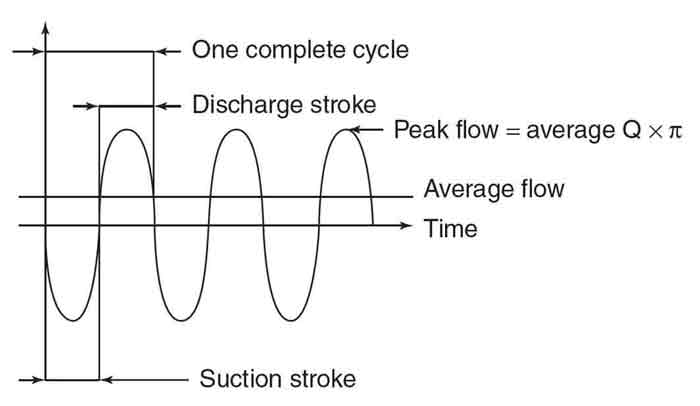
Figure 7.8.7.1. Example of pulsing flow (Graphics courtesy of Hydraulic Institute)

When connecting more than one pump head to a single suction manifold, operators must consider a number of issues. Suction manifold piping must accommodate peak demand of the pumps throughout its full range of operation, as well as prevent offgassing of liquids with high vapor pressure or dissolved gases. This is accomplished by appropriately increasing the diameter of the suction manifold and pump head connections or by adding accessories to increase flow of fluid to the pump inlet. The most important consideration is whether the multiple heads are part of a multiplex pump (multiple heads connected to a single motor or driver) or if the heads all have independent motors or drivers. In most cases, multiplex pumps are connected to a common manifold piping arrangement, driving these recommendations. The other option is to connect each pump head to its own suction line connected to the supply source.

In a multiplex where a single driver is used, if the pumps all operate from the same gear set or with multiple gear sets operating at the same stroking speed, industry best practices suggest that the drive mechanism for each individual pump head should be run out of phase (i.e. duplex pumps, 180 degrees; triplex pumps, 120 degrees; and so on). This staggers the peak suction requirements of the individual pumps.

Running several pumps from the same driver (motor) with proper phasing of the drive elements ensures this timing during all running conditions and the best suction flow characteristics as they relate to piping design.

When independent pumps, each with its own driver, are connected to a common suction line, or if the application requires multiplex pump heads operating in phase, operators must make allowance in the piping design in case all pumps simultaneously demand peak suction flow.

For more information on piping guidelines for control-volume metering pumps, refer to the new standard ANSI/HI 7.8 Control-Volume Metering Pump Piping Guideline.

Q. What are the requirements for good suction piping design for rotodynamic pumps?

A. Good suction piping design must eliminate air entrainment in the liquid, minimize friction loss, provide straight and uniform flow at the pump inlet, and avert excessive forces resulting from pipe strains at the pump.

Inlet flow disturbances such as swirl, unbalance in the distribution of velocities and pressures, and sudden variations in velocity can be harmful to a pump’s hydraulic performance, mechanical behavior and reliability.

Usually, the higher the energy level and specific speed of a pump and the lower the net positive suction head (NPSH) margin, the more sensitive the pump’s performance is to suction hydraulic conditions.

All inlet (suction) fitting joints should be tight—especially when the pressure in the piping is below atmospheric—to preclude air leaking into the fluid. Any valves in the inlet line should be installed with stems oriented to minimize the possibility of air accumulation. For pumps operating with a suction lift, the inlet line should slope constantly upward toward the pump, with a minimum slope of 1 percent (see Figure 9.6.6.3). For most pumping systems, a shutoff valve should be installed in the suction piping for system isolation.

Suction pipe design
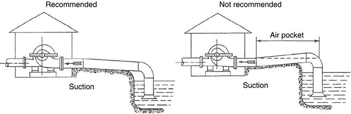
Figure 9.6.6.3. Suction pipe design

As liquid travels through a piping network, entrained air tends to rise to the highest point. If the pipeline slopes upward, then the liquid’s velocity will move the air bubbles toward this high point. In contrast, if the pipeline is fairly flat and the inside surface of the pipe is rough, or if the pipeline slopes downward, then the fluid velocity may not be sufficient to keep the air bubbles moving. As a consequence, a pocket of air could collect at high points and gradually reduce the effective liquid flow area. This reduction in area can create a throttling effect similar to a partially closed valve. A slug of air could be swept into the pump during a restart, causing a partial or complete loss of pump prime, especially where the inlet line is kept full by a foot valve at its intake. Any amount of entrained gas in the fluid may adversely affect pump performance. Check with the pump manufacturer to determine allowable levels of entrained gas.

The ideal flow entering the pump inlet has a uniform velocity distribution without rotation and is stable over time. This ideal flow is often referred to as undisturbed flow, and it can be achieved by controlling pipe lengths and the type and location of fittings in the suction piping system. The suction piping should be designed to be simple with gradual transitions if changing pipe sizes.

The velocity in the suction piping should be constant or should increase as the flow approaches the pump. Transitions resulting in flow deceleration at the pump should be avoided.

The suction pipe should be at least as large as the pump suction nozzle. Valves and other flow-disturbing fittings in pump inlet piping should be at least one pipe size larger than the pump inlet nozzle, with the exception of continuous-bore, 100-percent-open valves (such as full-ported ball valves).

The maximum velocity at any point in the inlet piping is 8 feet per second (ft/s), unless the liquid is a slurry. This velocity limit does not apply to the straight run of pipe immediately upstream of the pump suction flange provided this pipe is the same diameter as the pump suction flange and directly connected to the pump.

Individual values above 8 ft/s should be evaluated with respect to flow distribution, erosion, NPSH, noise, water hammer and the manufacturer’s recommendations.

For fluids close to the vapor pressure, the velocity must be kept low enough to avoid flashing of the liquid in the piping, especially when fittings are present. A reduction in pressure and/or flashing can liberate dissolved air and vapor, which can be carried into the suction of the pump.

For more information on piping requirements for rotodynamic pumps, refer to the recently revised ANSI/HI 9.6.6 Rotodynamic Pumps for Pump Piping.

See other HI Pump FAQs articles here.