
Fourth of Six Parts Just 20 years ago, many professionals did not consider using variable frequency drives (VFDs) in wastewater applications. Frequency converters were relatively expensive, and experience using them had not been very successful in light of the special conditions and requirements in wastewater. Today, VFDs are often used in sewage transport, even though some operations do not favor using them. However, flow control is necessary, and plants desire energy savings as well. While some plants have experienced trouble-free operation of these systems, sometimes detailed knowledge of how to use this equipment for a specific design or existing operation in wastewater is missing. With correct usage, VFDs can support trouble-free operation, but they also can disturb proper functioning of a well-designed pumping station. Because of the increase in wipe usage and the new challenges in sewage (as discussed in Part 1 of this series, Pumps & Systems, November 2015), it is even more important to consider the right exertion. Since 2010, there have been reports on the usage of VFDs and backward operation as a de-ragging method. In some cases it makes sense to use these tools, but they have some limits.
Checking Velocities
Often the question arises of what the maximum reduction of frequency would be for the motor on a submersible wastewater pump. For wastewater, the limits for the motor by itself are not relevant because the impact of the hydraulic limits occur much earlier. Many motors can be reduced in speed to half the nominal frequency without any problem. But the fluid dynamic would be in bad shape if the wastewater is pumped at the corresponding velocity for a longer operation time in the system. The necessary minimum velocity of the sewage initially limits the reduction of frequency for trouble-free operation. Depending on the kind of wastewater and the content, it is necessary to transfer enough energy into the liquid to transport the solids and fibers as well. The pump’s tip speed (speed outside of the impeller diameter), the velocity in the vertical pipe and the horizontal pipe, and the necessary velocity to open the check valve are important parameters to program into the VFD to ensure the velocity during operation is not too low. Exact detailed values generally cannot be given mathematically. The different loads over time and in different stations create a gray area. However, they are good enough for raw sewage in the first implementation to prevent breakdowns. If the velocities in operation are not below the recommended minimum velocities, the risk of blockages is minimized.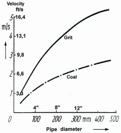 Figure 1. This shows average values from the practice of transporting grit or coal in horizontal pipes in a mixture 20 to 25 percent per volume. Necessary velocity is a function of the pipe diameter. (Graphics courtesy of KSB)
De-Ragging Function
The above recommendations are the most important for VFD usage in raw sewage and can substantially minimize the risk for clogging. However, additional capabilities are offered by some VFD suppliers. The so-called de-ragging function offers change of speed and/or backward operation of the pump. One of the main problems with the de-ragging function is the braiding fibers, which can form rag balls. Rag balls up to 24 inches have been common. Avoiding formation of these rag balls at an early stage is critical. A fast reaction of changing speed or backward operation may be required. Otherwise, the large rag ball may grow, and even if it could be flushed back out of the pump or pipe, it remains in the sump and cannot be pumped through. Before the backward-operation function can be used, the pump manufacturer should be consulted for the particular hydraulic to confirm that backward operation will not damage the specific pump. Avoiding velocities that are too low in the system is the basis for lower risk of clogging. It would not make sense to have a de-ragging (backward) feature without this fundamental concept. In several tests, just a change of speed helped to dismiss the initial clogging situation. If the speed is on the lowest end and clogging is indicated, it makes sense to ramp up the pump. If clogging is indicated during nominal speed (wipes on the vane), it can help to slow the pump down to get rid of the rag from the vane, then increase to nominal speed.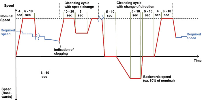 Figure 2. This graph shows the sequences for the described process of de-ragging speed over the time.