
09/29/2012
"Testing Centrifugal Pumps in the Field,” Pumps & Systems, February 2011, featured an Excel spreadsheet designed to simplify the field test procedure. The equation for total dynamic head (TDH) showed the components that led to its calculation. One of those components is velocity head, and I have received several requests to revisit its effect on a pump’s TDH when tested in the field. This month is perfect timing since we spent the last two months discussing the achievements of the man who defined it—Daniel Bernoulli.
Velocity Head & Discharge Pressure
Velocity head can be an important component when measuring the discharge pressure of a pump in the field. After all, the bourdon tube pressure gauge measures pressure just like a piezometer and measures only the static pressure. In some instances, velocity head can contribute significantly to the TDH. If it is not taken into account, an accurate comparison of the field test data to the manufacturer’s test curve is not possible. The location at which a gauge reading is taken can have a significant effect on the actual pressure reading. It is not unusual for a centrifugal pump to be connected to a pipeline that is sized for low friction losses via a short length of pipe that is the same size as the pump discharge. If the discharge pressure is measured in that section, it can be different than a measurement taken on the larger diameter pipe. For example, many pumps with 3-inch discharges can produce flows of more than 700 gallons per minute (gpm), and 4-inch models can exceed 1,100 gpm. In fact, almost all pump sizes are capable of flows that exhibit extremely high discharge velocities. When this occurs, velocity head becomes an important component when measuring TDH.Examples
Let’s take a look at a couple examples. A 3x4x9 end-suction pump operating at 3,500 rpm is connected to the flanged concentric increaser shown in Figure 1. The gauge located on the short section of the 3-inch diameter pipe reads 107 psi (247 feet). A flow meter, installed downstream in the 5-inch diameter section, measures a flow of 650 gpm. When we compare these measurements to the manufacturer’s H/Q curve, this pump should be producing 650 gpm at 112.5 psi (260 feet). The indication would be that this pump does not meet the manufacturer’s test conditions. Now, suppose we do not have a flow meter, and we use the pressure measurement to find the flow point on the H/Q curve. A head of 247 feet would show a flow of 740 gpm. Neither method provides the actual pump performance.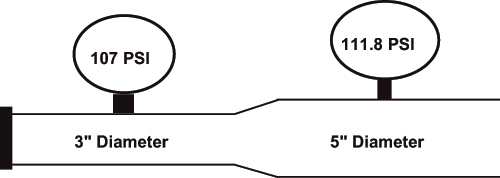 Figure 1. A concentric increaser