Variable frequency drives (VFDs), also referred to as adjustable-speed drives, drives, inverters and other terms, continue to grow in popularity in motor applications. The technology offers improved energy efficiency and lower operating costs, but unfortunately the high frequency currents can cause motors to be susceptible to bearing failures. This, in turn, can cause early motor failure, which can shut down pumping operations and become a costly problem.
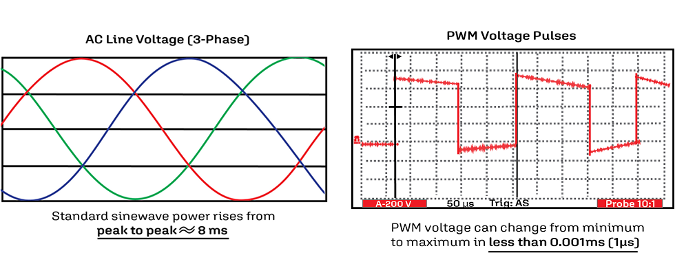
Bearing failures have increased mainly due to the fast-rising voltage pulses and high switching frequencies of VFDs. These current pulses will find the path of least resistance to ground, and that path is usually through the bearings, where the repeated discharging of these currents will gradually damage the bearing races.
Generating Bearing Currents
Bearing currents have long been an issue with alternating current (AC) motors. However, improvements in engineering, motor design and manufacturing practices have mostly eliminated the low frequency bearing currents associated with normal sine wave motor operation.
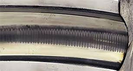
VFDs, on the other hand, typically generate high-frequency current pulses due to the rapid switching abilities of the semiconductors used in electrical conversion. These high frequency pulses cause damage and etching of the bearing and races and remove metal from the ball bearing. This metal transfers from the ball and the races to the lubricant and results in electrical discharge machining (EDM). The damage to the bearing, or EDM pit, causes a deformity in the surface of the bearing, which will draw more pulses and create EDM fluting.
High-Frequency Bearing Currents
The source of bearing currents is the voltage that is induced over the bearing. This voltage can be generated in several different ways.
1. Circulating current
Voltage is induced between the ends of the motor shaft by the high-frequency flux circulating around the stator. If the voltage between the shaft ends is high enough to overcome the resistance of the oil film from the grease or the bearing oil film, a current starts to flow in the loop formed by the shaft, the bearings and the stator frame.
2. Shaft grounding current
The current leaking into the stator frame needs to flow back to the inverter. This is the source of the grounding current. If the motor shaft is grounded through the driven machinery and the voltage becomes high enough to overcome the resistance of the drive-end bearing oil film, part of the current may flow through the drive-end bearing, shaft and driven machine.
3. Capacitive discharge current
In small motors, the internal voltage division of the common mode voltage over the internal stray capacitances of the motor may cause shaft voltages high enough to create high frequency bearing current pulses. This can occur if the shaft is not grounded through the driven machinery while the motor frame is grounded in the standard way for protection.
4. Common mode circuit
Under normal conditions, a three-phase power supply is balanced and symmetrical. This is not the case with a pulse width modulation (PWM) switched three-phase power supply, where a direct current (DC) voltage is converted into three-phase voltages. This voltage can be defined as a common mode voltage. The current can flow back to the source through the grounding conductor and stray capacitances of the inverter; the current flows in a closed loop that is external to the system.
5. Stray capacitances
A capacitance is created any time two conductive components are separated by an insulator. For instance, the motor winding turn is insulated from the motor frame by enamel coating and slot insulation and has a value of capacitance to the motor frame. Modern power supplies produce fast-rising pulses that contain high frequencies. Because of these high frequencies, the small capacitances inside the motor still provide a low resistance path for current to flow. This can lead to the creation of stray currents that can damage bearings.
Preventing High-Frequency Bearing Current Damage
There are several approaches used to affect high frequency bearing currents.
Proper cabling and shaft grounding systems, electromagnetic filters and damping the high-frequency common mode current are the most commonly used means of limiting bearing and motor damage due to excess currents and stray voltage, as well as voltage spikes associated with VFDs.
The easiest way to avoid bearing damage from stray currents is to provide a path to ground that allows stray currents to return to the inverter frame without passing through the bearings. Symmetrical motor cables or inverter output filtering can reduce the intensity of the stray currents. An insulated bearing is another component that can be used to interrupt the current path.
Several solutions are available to protect the motor from high common mode current frequencies, including the following:
Grounding brushes: This method channels the current away from the bearings and significantly reduces shaft voltage and bearing current by not allowing voltage to build up on the rotor.
Insulated bearings: These bearings reduce or eliminate the path to ground through the bearing but do not eliminate the shaft voltage, which can potentially cause issues if that path is through the driven load or some other component. For this reason, grounding straps or cables are necessary.
Shaft grounding rings: These rings can be placed on either end of the shaft (Image 3).

Multicore motor cables: Only symmetrical multicore motor cables should be used. Proper grounding cables should have a conductor surrounding all the phase leads or a cable.
Short impedance path: The impedance path is shortened when using shorter cables. Shielded motor cables are the best and easiest option for this.
High frequency bonding connections: Braided straps of copper 50-100 millimeters (mm) wide are recommended. This will provide a lower inductance path than round wires.
Output filters: A sine filter is installed between the output of the VFD and the motor and should be installed as close as possible to the VFD. Sine filters are normally used when long motor leads are required. An output choke in an inductor system reduces the voltage rise time at the motor and protects the motor’s insulation system. It can also help reduce the motor’s operating temperature.
Protecting Bearings for Longer Motor Life
High frequency currents, fast-rising voltage pulses and high switching frequencies of VFDs will find the path of least resistance to ground in an unprotected motor. This path is usually through the bearings.
To prevent the breakdown of the bearings and eventual damage to the motor, it is important to identify any stray currents and high voltage discharges and protect against these occurrences. Installing inverter duty motors and following the guidelines for protecting systems when using VFDs are the best practices for preventing bearing and
motor damage.
For more on VFDs, visit pumpsandsystems.com/tags/vfd.