
How fluid drive, eddy current drive and wound rotor motors work to achieve true variable speed control.
Senior Pump System Engineer
02/20/2019
To achieve true variable speed control of a centrifugal pump, this article will look at the following methods or technologies: fluid drive, eddy current drive, wound rotor motor, adjustable voltage direct current (DC), adjustable frequency alternating current (AC), magnetic drive and steam turbine. Part 1 of this article will focus on fluid drive, eddy current drive and wound rotor motor. Part 2, which will be published in an upcoming issue, will focus on electronic speed control drives, adjustable frequency drives, magnetic drives and steam turbine drives.
Fluid Drive
Variable speed fluid drives, known as hydro-kinetic, are typically used in high horsepower (hp) applications. However, this type of fluid drive can be made from a few horsepower to over 40,000 hp. For horsepower ratings under this level, other methods of speed control are generally used. It should be noted the terms fluid coupling and hydraulic coupling are sometimes used interchangeably with fluid drive. In most applications, a variable speed fluid drive is driven by a constant speed motor of either induction or synchronous type and delivers variable speed power to a process pump. The fluid drive output shaft speed (pump speed) is controllable in step-less speed changes in a range, typically, from 20 to 97.5 percent of the input shaft speed. The output shaft speed is extremely smooth, eliminating torsional excitation pulsations. Fluid drive technology is still popular for boiler feed and fan applications such as forced and induced draft. It should be noted that every type of variable speed drive can be used with a constant ratio gearbox to achieve the actual speed range desired by the pump application. However, the only type of variable speed drive that includes a gearbox within the drive is the type called “variable speed geared fluid drive.”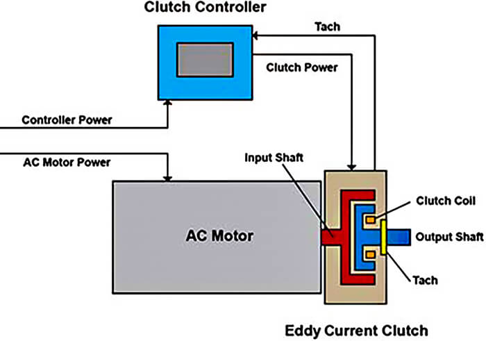 Image 1. Fixed speed motor and eddy current clutch. (Images courtesy of the author)
Eddy Current Drive or Coupling
An eddy current drive, also known as electo-mechanical drive, consists of a fixed speed motor and an eddy current clutch. The clutch contains a fixed speed rotor and an adjustable speed rotor separated by a small air gap. A DC in a field coil produces a magnetic field that determines the torque transmitted from the input to the output rotor. The controller provides closed-loop speed regulation by varying the clutch current, allowing the clutch to transmit enough torque to operate at the desired speed. Speed feedback is provided by an integral AC tachometer. By regulating voltage to the clutch coil, a magnetic flux field is generated in the gap and distortion of the flux field creates torque. Output speed is governed by the digital control. The greater the power is to the clutch coil, the greater the strength of the magnetic flux field, and the greater the output torque or speed. The tachometer’s feedback signal is compared to a reference signal within the controller to maintain accurate speed within 0.5 percent. This closed-loop speed system typically uses less than 1 percent of the total AC input current to the motor. The only wear parts are bearings and brushes, since the motors and drives are separated by an air gap.Efficiency
Eddy current drives use a DC magnetic field to link two members, one on the input shaft and one on the output shaft. Increasing the DC to the coil increases the coupling of the two members, thus delivering more torque to the load. A tachometer is used to control the velocity and torque. Eddy current losses in efficiency in an AC motor are equal to nameplate rating as the motor is running across the line. This is true for power factor and efficiency. With DC control losses in efficiency are typically 2 percent or less. And in a slip the reduction in speed is dissipated in the drum and rotor (the coupled members). It reduces efficiency in proportion to reduction in speed. It is best to run an eddy current device at or near rated speed. Typically, 82 to 100 percent is best to optimize efficiency.Maintenance
Bearing lubrication is needed to maintain an eddy current drive. The control, which can be a single printed circuit board, requires no maintenance. A typical eddy current drive should last 40 years.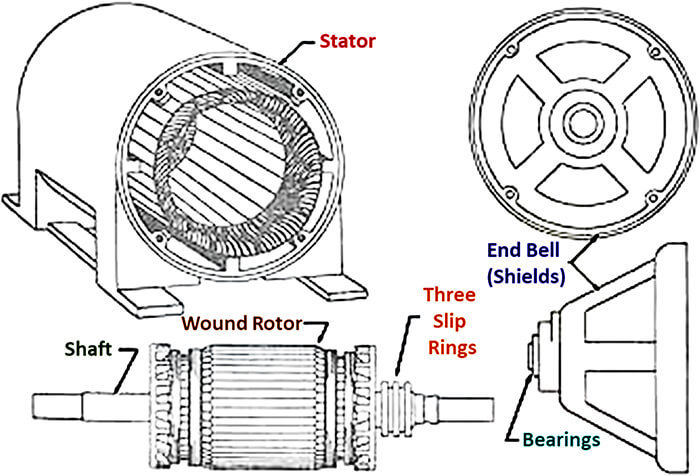 Image 2. By changing the external impedance connected in the rotor circuit, the speed or current and speed or torque curves of the induction motor can be altered.