
Editor’s Note: This article originally appeared in the November 2007 issue of Pumps & Systems.
This past summer I received a suggestion from a Pumps & Systems reader to discuss siphons and their effect on pump head and pipeline flow. If you are like me, your first experience with one of these devices probably led to your first - and hopefully last - taste of gasoline. The siphon is an example of a natural and extremely simple machine that we take advantage of daily.
Their earliest known use dates back to the Egyptians around 1500 BC, but the siphon principle was not described until about 240 BC. The man credited with this work was the Greek mathematician and inventor Tesibius of Alexandria. He was known for three major inventions: the piston pump, the water clock, and the hydraulis, which was the ancestor to the pipe organ. All of his written works have been lost, but his successors refer to him in their writings as the "father of pneumatics."
True Siphons
There are several definitions of a siphon. The Pump Handbook provides a couple: one explains it as "a pipe or other closed conduit that rises and falls," while a more specific definition refers to "a jet pump that utilizes a condensable vapor as a motive fluid." Both can be examples of the siphon effect, but neither describes exactly how I was able to transfer gasoline from my dad's car to our lawnmower (and my mouth).
I define a "true" siphon as a tube or pipe through which a liquid can be moved from a higher to a lower level by atmospheric pressure forcing it up the shorter (or up) leg while the weight of the liquid in the longer (or down) leg causes continuous downward flow. One of the key phrases in this definition is "continuous flow" - this separates the true siphon from the siphon effect that may occur in a piping system.
Although the siphon appears quite simple, there is still some debate as to how it actually operates. Gravity obviously causes a liquid to flow through the down leg, but what causes it to navigate the up leg?
If you submerge the end of a long tube in a container of water, the water within the tube will rise to a level equal to its surface level in the container. If you were to evacuate all of the air in the tube, the level inside would rise to a level equal to the atmospheric pressure pressing down on the surface of the container.
The traditional explanation of a siphon states that the flow in the down leg, due to gravity, creates a partial vacuum in the upper most portion of the conduit. That partial vacuum allows atmospheric pressure to initiate flow through the upper leg. This sounds reasonable, but there is quite a bit of debate as to the effect the cohesive forces of the liquid molecules have on maintaining flow. I think it is reasonable to expect that both cohesion and a partial vacuum play a role.
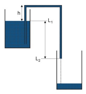 Figure 1. The layout of a simple siphon. (Figures courtesy of The Central Arizona Irrigation Project)
Here we see water flowing from an upper reservoir and discharging into a lower one. For a siphon to flow continuously, the height of the upper leg (h) must be less than atmospheric pressure and the outlet of the down leg (L2) must be below the surface of the upper reservoir (L1). The siphon conduit must also be completely full and free of air and liquid vapor. If any of these conditions are violated, the siphon will cease to operate. Under ideal conditions and an atmospheric pressure of 34-ft (sea level), the maximum height of the upper leg is limited to about 33-ft.
So, if you had to guess, what is one of the most common uses of a siphon that we see every single day? It is "The Silent Valveless Water Waste Preventer," patented in England in 1819 and better known today as the flush toilet.
If you look at the side of many modern toilets, you can actually see the outline of the siphon conduit. The height of the upper leg dictates the static water level in the bowl. When the flush valve is opened water flows from the tank into the bowl, the water level rises, and water begins to flow into the down leg. Once the down leg is completely full, the system becomes a true siphon and ends with that sucking sound when the tank and bowl are empty.
The "J" trap beneath your bathroom lavatory is often referred to as an "inverted" siphon, but it is not a siphon at all. It relies on the weight of the water in the longer down leg to force the water though the shorter up leg. Once the lavatory has completely drained, some water remains in the lower, curved portion of the trap and prevents sewer gases from sneaking back through the drain.
Some of the finest examples of inverted siphons can be found in Hawaii. Constructed in the late 1800s and early 1900s, they carry water from irrigation ditches across beautiful valleys that were too wide for overhead aqueducts. Inverted siphons are also quite common in water and sewage transmission lines that must dip down to go under a highway or some other obstacle and then rise again on the other side.
It is not surprising that true siphons are used extensively to move water from one location to another. After all, the energy required to operate them is free and it is often less costly to construct an above ground piping system. The two photos below shows an innovative application using multiple siphons to move water from an irrigation ditch. Each siphon feeds a separate furrow and negates the requirement for sluice gates or other methods of channeling the water.
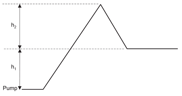 Figure 2. A piping system illustrating siphon effect
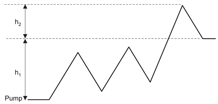 Figure 3. A pipeline with up and down legs
Large siphons are used extensively throughout the world in high volume flow applications. In the U.S., many water and irrigation aqueducts use a combination of pipelines, tunnels, siphons, inverted siphons, channels, and ditches to move water many miles from its source to its point of use.
The Siphon Effect
As long as a pipeline is flowing full, the pump head required to maintain flow is equal to the head due to friction and the elevation increase between the pump discharge and the pipeline discharge. This rule holds true even if some point in between has an elevation greater than that of the pipeline discharge.
Figure 3 shows a simple piping system that illustrates this rule. The reason that the higher elevation (h2) seen between the pump and pipe discharge does not affect pump head is due to head recovery provided by the "siphon effect."
Now, h2 must be accounted for when filling the line, but once it is flowing full the down leg will cancel its additional height and the elevation seen by the pump will be h1. If the down leg is not flowing full, the head required will be that of friction plus the sum of h1 and h2. The major difference between a true siphon and the siphon effect is the latter will not maintain flow by itself.
A pipeline with several up and down legs in series. In this example, each down leg produces a siphon effect and the total head seen by the pump, once the line is filled, is equal to h1 plus the friction in the line due to flow.
Although piping systems that rise and fall can take advantage of the siphon effect, they are also vulnerable to entrained or dissolved air accumulation at their high points. If not properly vented, air pockets can reduce and, in some cases, completely prohibit flow through the system. The chance of this occurring is increased in piping systems with multiple up and down legs. If some air is trapped in these upper areas but flow is maintained, the elevation head required to maintain flow will be h1 plus the sum of the heights of the air pockets in each down leg.
Reprints from classic Pumps & Systems articles fill a gap in our industry: basic information for new pump users. If you have a go-to article for training new employees or refreshing yourself on the basics, please tell us about it at pumpeditors@cahabamedia.com.
