
Currently, two test procedures could be requested to qualify a quarter-turn valve design for fugitive emissions service: International Standards Organization (ISO) 15848-1 (2nd Edition, 2015) and American Petroleum Institute (API) 641 (1st edition, 2016). Both standards are technically viable options that can be used for valve qualification. Both could be considered good engineering practice since they clearly spell out conditions and procedures that help ensure the test is repeatable, and that it can be considered representative of the valve’s real life operating conditions. Either protocol can qualify valves for higher temperature service where graphitic seals are typically used and lower temperature service where PTFE-based seals are usually used. The general process used by both standards is as follows: the valves are set up with blank flanges on both ends; fittings are installed on the blanks to allow the valve to be internally pressurized with test media (methane gas at 97 percent purity minimum as the standard in the U.S.). The static joints on the valve (i.e. bonnets and/or flange gaskets) are tested for leaks before starting the actual test. The valve is pressurized with the test gas, and the valve stem is then actuated a specific number of open and close cycles at ambient temperature. Leakage measurements are taken at prescribed intervals using a calibrated leak detection unit that meets specific requirements spelled out in the standard (e.g. sensitivity, response time, etc.). Then, the valve is heated to an elevated temperature, which is determined ahead of time and is based on valve design and materials used and the stem cycling and measurement process is repeated. This cycle of ambient and elevated temperature operation is repeated a number of times. The number of thermal cycles depends on the standard used.
Differences Between ISO 15848-1 & API 641
There are a number of major differences between ISO 15848-1 and API 641 that may steer a manufacturer or end user toward using one test method over the other. The key differences can be grouped into the following: test conditions, number of stem and thermal cycles, valves qualified under the standard, related valve design standards that may reference either of the above referenced test methods and the end user’s specification. The ISO procedure allows for the use of two different test gasses, helium and methane, each with different leakage measurement methods. In the ISO test, helium is measured by essentially bagging the test valve and measuring the mass leak rate of helium leaking through the packing set. If methane is used, leakage from the packing set is measured as a concentration (in parts per million by volume [ppmv]) using a vapor analyzer and ‘sniffing’ around the packing set. The ISO standard specifically states “… there is no correlation intended between measurements of total leak rate … and local sniffed concentration.” Also, since helium is generally not accepted as a suitable test medium by enforcement agencies in the U.S., and because current field monitoring techniques are done using ‘sniffing’ and not ‘bagging,’ only the methane portion of ISO 15848-1 would generally be considered a viable option for leakage measurement for valves destined for the markets where API valves are used or specified. The API 641 protocol uses methane and ‘sniffing’ only.Temperature
Both standards are written so they can be used for qualification of valves using seals intended for high temperature service as well as for other valve designs and materials intended for lower temperature services that may be sealed with non-graphitic seals (e.g. PTFE packing or v-rings). API 641 has two temperature groups: valves intended for services above and below 500 degrees Fahrenheit (F) (260 degrees Celsius (C)). For the high temperature group, the maximum test temperature and pressure is 500 F (260 C) and 600 pounds per square inch gauge (psig) or a gauge pressure of 41.4 bar. Valves for lower pressures are tested at their allowable rating and at the 500 F (260 C) test temperature. The lower temperature valves are tested at their maximum temperature rating using the corresponding pressure rating at that temperature. The maximum test pressure is 600 psig (41.4 bar[g]). The maximum temperature and pressure ratings in API 641 correspond to the values used in API 622 and 624 testing. These limits are to ensure safety in the laboratory using methane at high temperatures. ISO 15848-1 follows a similar methodology using two defined temperature limits—400 C (752 F) for high temperature valves typically sealed with graphitic seals and 200 C (392 F) for the lower temperature valve applications. The test pressure is based on the maximum rated pressure of the valve at the chosen test temperature. As noted earlier, the ISO test can be done with either methane or helium. However, most test facilities will only do the 400 C testing using helium gas given the safety concerns with methane. The ISO standard also defines cryogenic temperatures for testing, -46 C (-50.8 F) and -196 C (-320.8 F), whereas there are no cryogenic parameters spelled out in API 641. API 641 calls for three full thermal cycles; during each cycle, the valve stem is actuated 100 stem cycles at ambient temperature and 100 stem cycles at elevated temperature. The valve is allowed to cool overnight and the process is repeated until completion, with a final 10-stem cycles at ambient temperature conducted before the final emissions reading. The test is considered passed if there are no emissions readings above 100 ppmv through the test and no stem adjustments to the packing gland are applied. Also, note that the API standard does not specify the type of service for which the valve is intended, i.e. control valve service or on/off (isolating) service. ISO does a similar process of ambient and elevated temperature cycling, but it details two specific endurance classes, each with three stages. For valves intended for on/off service, the class ‘CO’ is used. CO1 is two full thermal cycles, each with 50 stem cycles (fully open to fully closed) at ambient and 50 at elevated temperature; 10 ambient cycles are done at the end of the two full thermal cycles/stages. CO2 is a continuation of CO1 with 790 stem cycles at ambient and 500 stem cycles at elevated temperature (for a total of 1,500 stem cycles). CO3 extends from CO2 with 500 stem strokes at ambient and then 500 at elevated temperature for a total of 2,500 cycles. For control valves, the three levels are CC1, CC2 and CC3. CC1 is 10,000 cycles at ambient followed by an equal amount at elevated temperature, CC2 continues with 20,000 more cycles at ambient and 20,000 at elevated temperature and CC3 repeats CC2 once more. In CC testing, all stem cycles are plus-10 percent of their stroke or angle from the midpoint of the valve stroke or angle. Speed of the stem is also dictated to be 1 to 5 degrees per second. One packing gland adjustment is allowed in each endurance class level (i.e. one in CO or CC1, an additional adjustment in CO2 or CC2, etc.). The ISO standard contains multiple leakage classes as well. If we consider only methane for the purposes of comparison to API 641, ISO specifies leakage classes- AM (≤50ppm), BM (≤100ppm) and CM (≤500ppm).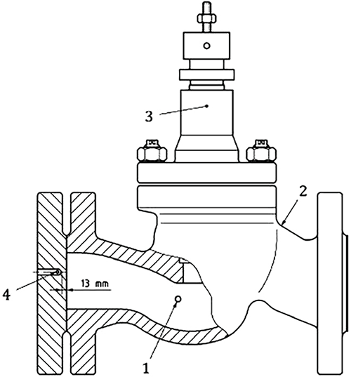 Image 1. Valve measurement location diagram (Image courtesy of the author)