Although a number of AC motor designs are used, the induction motor is, by far, the most common and will be the topic of this column. We will also focus on the three-phase design as it provides a more intuitive understanding of induction and the magnetic fields that are produced. We will discuss the operation of single phase motors in the May 2011 issue.
Components
The AC induction motor was invented by Nikola Tesla, the Serbian-American engineer who helped George Westinghouse win the war of the currents. Although his design has been enhanced through the years, simplicity is still its hallmark. The three-phase motor consists of two basic parts—a stationary component known as a stator and a rotating component known as a rotor. The stator consists of coils of insulated wire wound about a laminated metal core that become electromagnets when power is applied.
The rotor also has a laminated metal core with conductive aluminum bars set in slots. These bars produce an induced magnetic field that interacts with the ones in the stator. The rotor and stator do not touch, and unlike the DC motor, AC motors contain no brushes or other commutative devices.
Figure 1 shows the stator mounted inside the motor housing or enclosure and the rotor mounted on the motor shaft. The junction box on the top of the motor housing connects the incoming three-phase power to the stator coils.
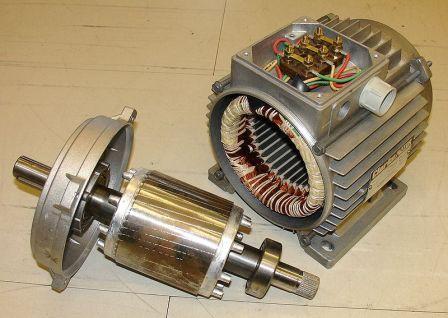 |
| Figure 1. Stator, rotor and motor housing |
Induction
Just like the transformer, AC motors operate via the principle of induction. In our discussion of AC Power in the fall 2010 series, we learned that when voltage and current move through a coil of wire, they create a magnetic field. We also learned that the magnetic field produced can induce a voltage and current in a nearby coil, and the result was a simple transformer.
This phenomenon of inductance is not limited to just a nearby coil. It can occur in any metallic object. In the case of an AC motor, the magnetic field created in the stator coils can induce a voltage and current in the conductive bars of the rotor. That voltage and current will produce its own magnetic field, which then interacts with the field that produced it.
The speed at which the magnetic field moves (rotates) around the stator is known as the synchronous speed and depends on the AC frequency and the number of poles in the stator. It is calculated by
Ns = 120f / P
Where:
Ns = synchronous speed
f = frequency
P = the number of poles in the stator
For a two pole motor operating at 60 Hertz, the synchronous speed is 3,600 rpm. If you increase the number of poles to four, the speed is reduced to 1,800 rpm. The speed at which the rotor rotates is known as the slip speed and will always be less than the synchronous speed in the stator. The reason for this is because no voltage and current is induced in the rotor when they travel synchronously. The actual slip speed depends on the motor design and will vary by model and horsepower. For fractional horsepower motors at full load, slip speed can be as low as 95 percent of Ns, while higher horsepower models can operate at 99 percent of Ns.
As discussed in my series on AC Power, the single phase AC sine wave reaches its peak voltage twice during one 360-degree cycle, and these peaks occur at 180-degree intervals. In a three-phase circuit, Phase 2 lags phase one by 120 degrees, and Phase 3 lags phase two by 120 degrees. When all three phases flow together, the voltage peaks every 60 degrees.
This relationship is illustrated in Figure 2. The arrows show the 120-degree separation of the three phases, and the vertical, colored lines show the phase voltages peaking every 60 degrees. This peaking relationship not only provides for a more uniform power supply but also can produce a rotating magnetic field in the stator of a three-phase motor.
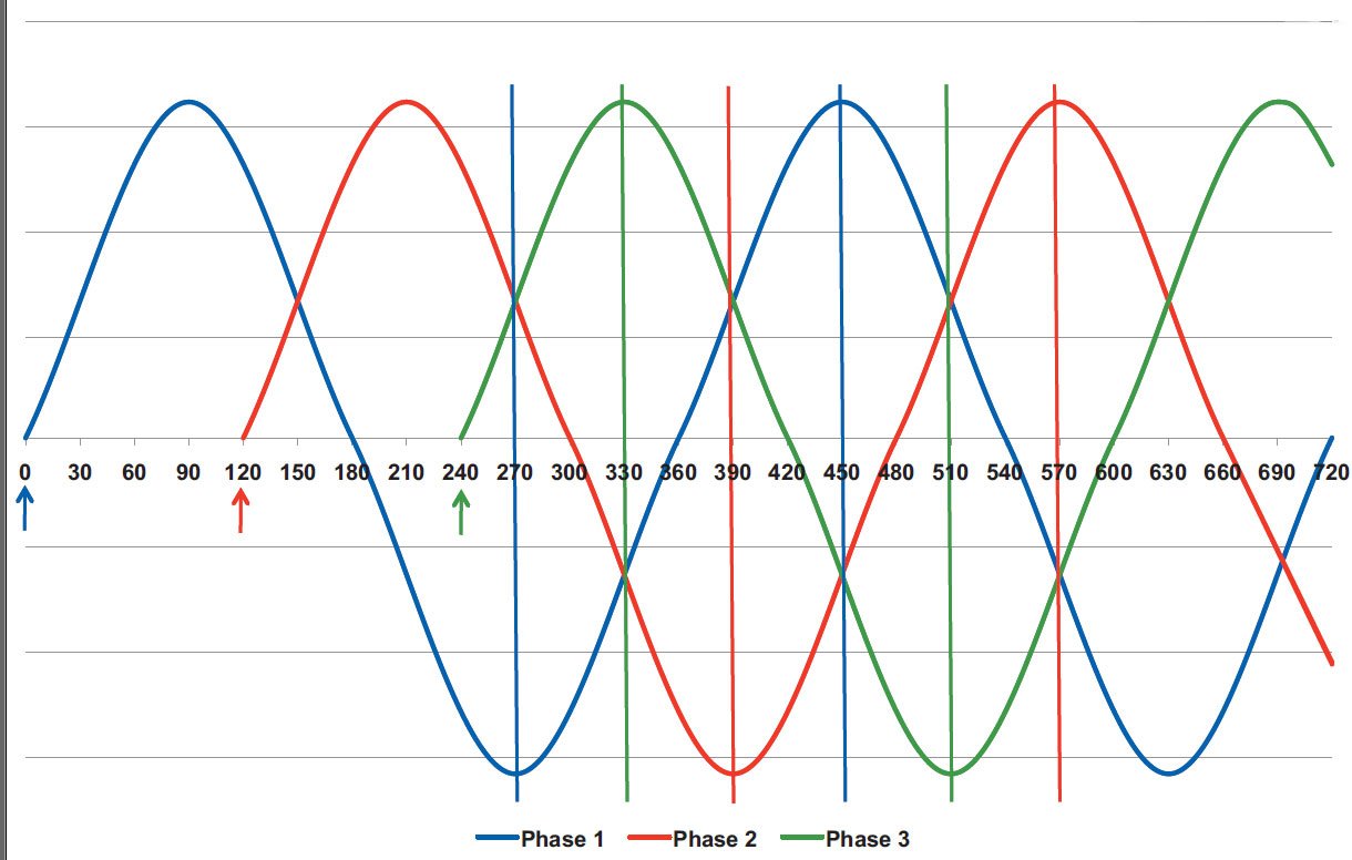 |
Figure 2. Three-phase AC motor sine wave and voltage peaks |
Figure 3 shows the pole placement for a three-phase, two-pole motor. As you will note, there are a total of six poles or two poles per phase. The Phase 1 poles are located at 360 and 180 degrees while the Phase 2 poles are at 300 and 120 degrees. The Phase 3 poles are located at 60 and 240 degrees. The result is a total of six poles spaced 60 degrees apart. This 60 degree separation is not a coincidence. It is done specifically to take advantage of the 60 degree separation of the three-phase voltage peaks. I will discuss why in the next section.
Now, you may be wondering why the phase poles are in this particular sequence. The primary pole of Phase 2 is to the left of the Phase 1 primary and the primary pole of Phase 3 is to the right. If you refer back to Figure 2, you will see that the peak following the Phase 1 peak is Phase 3, and the next peak is Phase 2. Motors are wound in this fashion to provide a predictable rotational direction.
In this particular case rotation would be clockwise. Reversing any two of the phase connections will change the phase peak relationships and cause the motor to rotate in the opposite direction. “Rolling” those connections (for example, moving 1 to 2, 2 to 3 and 3 to 1) will not change the phase relationships, and therefore, the direction of rotation will remain the same.
The Rotating Magnetic Field
We have seen how the voltage can peak in a three-phase circuit and how the stator poles are aligned to match voltage peaks, but why does the rotational magnetic field occur automatically? Figure 4 puts the linear flow of voltage peaks shown in Figure 2 and the pole locations shown in Figure 3 into a rotational perspective.
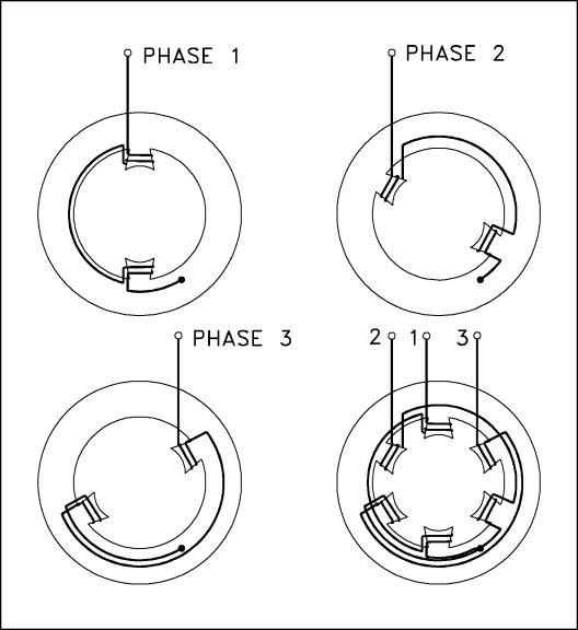 |
| Figure 3. AC motor pole placement |
The stator images show the three sets of poles and their polarity from Points 1 through 7. The graph image shows the phase voltage peaks for the same points.
At Point 1, Phase 1 is at its positive peak and a maximum magnetic field is generated in Poles 1 and 1A. At Point 2, Phase 3 is at its negative peak and the maximum magnetic field is generated in Poles 3 and 3A. At Point 3, the maximum field has moved to Poles 2 and 2A.
If you study the other points you will see that this trend continues in a clockwise direction. As a result, the three phases create an automatic rotating field in the stator. If any two of the incoming phase leads are switched, the magnetic field will rotate in a counterclockwise direction.
.jpg) |
Figure 4. The rotating magnetic field |
As mentioned earlier, motor speed depends on both frequency and the number of poles. Motor speed will change in direct proportion to a change in frequency. For example, at 30 Hertz an 1,800 rpm motor will rotate at 900 rpm.
If an additional set of poles is added to each phase of the stator shown in Figure 3, its speed will also be decreased by 50 percent. The time required for one 360-degree rotation of the stator field is proportional to both frequency and the number of poles.
Three-phase motors can be designed to operate at two different speeds, and the speed relationship depends on the winding method employed.
Two-speed, single-winding motors use a stator that is wound for a single speed, but when the winding is connected in a different manner, the number of poles connected is also changed.
For example, in one connection,four poles are connected, but with the alternate connection, eight are connected.
With this winding method, a two to one speed relationship (1,800 rpm/900 rpm) will always exist. Usually, the brake horsepower (BHP) at the low speed will be one quarter that of full speed. However, constant torque designs will maintain one half BHP at the lower speed.
Two-speed, two-winding motors are actually two motors wound on a single stator.
Although these motors are typically larger and more expensive, they are not limited to the two to one speed relationship of single winding motors.
For example, a four- and six-pole, two-winding motor would produce speeds of 1,800 rpm and 1,200 rpm. In this example, the BHP at the low speed will be two thirds that of full speed. Next month, this column will investigate the operation of single phase motors.
Pumps & Systems, April 2011
Click the links below for the rest of the AC Motors series:
AC Motors: Magnetism and the DC Motor
AC Motors Part 3 - Single Phase Operation
AC Motors Part 4: Frame Size, Enclosures & Nameplate Data
AC Motors Part 5: AC Motor Life
AC Motor Torque