
Pumps & Systems, June 2007
Most of the electric motor information we use on a daily basis is pretty straightforward. Voltage, amps, efficiency, and service factor are all well understood terms in our industry. There is, however, one motor characteristic that can be anything but straightforward. That characteristic is power factor (PF).
Part of the confusion is due to the unfamiliar terms that are used to explain PF. Apparent power, real power, reactive power, and kilovolt amps reactive (KVAR) are several examples. Some tutorials even require you to dust off that old trigonometry book and compute the cosine of theta! Lost that old trig book? No problem - pull out that old geometry book and use the Pythagorean Theorem!
Let's take a look at power factor from a more basic perspective and see if we can make it a bit more meaningful.
In the larger view, power factor refers to the portion of the power in a circuit (building, plant, process, etc.) that can actually be used by electrical equipment compared to the total amount that is supplied by the utility. Expressed another way, it is the power consumed (measured in watts) versus the total power available (measured in volt-amps). But wait, isn't a watt a volt-amp? We will see shortly that the answer is not always.
Power factor can also be used to describe how effectively an inductive device, such as an electric motor, uses the power that is available in a circuit. Notice that I said "effectively" and not "efficiently." We use efficiency to describe how well a motor converts electrical energy into mechanical energy. PF is a dimensionless number that ranges from zero to one and is often expressed as a percentage.
For example, a PF of .8 or 80 percent would indicate that the motor could effectively use 80 percent of the energy available. But that other 20 percent is not necessarily wasted. It is just unusable by the motor and all other electrical devices in the same circuit! So why can't a motor use all of the available power in a circuit and, more importantly, why does it really matter? Let's investigate.
The mystery begins with the difference in the way AC power is delivered and measured. It is delivered as volts and amps, but it is measured in watts. In a simple DC circuit, a watt is a volt-amp or volts multiplied by amps. One volt times one amp equals one watt. The voltage (E) and the current (I) in the circuit follow a simple relationship known as Ohm's law (E = I x R or I = E/R, where R is the resistance to the flow of current in the circuit).
Unfortunately, it is not always this simple in an AC circuit. In AC, R is replaced by a more complex value known as impedance (Z), which is a combination of resistance and another element called reactance. Reactance also consists of two parts - inductive reactance and capacitive reactance, which are sometimes referred to as "imaginary" components! Imaginary or not, these two reactive components added together determine how much of the voltage and current in an AC circuit is consumed in the form of a watt.
The power consumed in a purely resistive AC circuit (incandescent lights, resistance heaters, etc.) tends to follow the simple rules of DC. Figure 1 shows voltage and current in a resistive circuit traveling in sync or in phase. By in sync, I mean that the current and voltage curves rise and fall together. If voltage rises, current rises by a proportional amount.
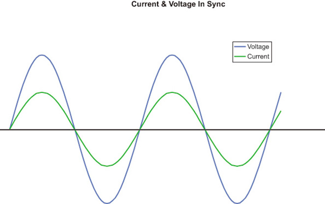 Figure 1
When voltage begins to fall, current will begin falling at the very same instant. When the curves are in sync, the power consumed in watts is volts times amps, and the product will always be a positive number. If both values are positive (above the X axis), we get a positive value for watts. If both values are negative (below the X axis), we still get a positive value because minus times minus is plus. If the load is not purely resistive and contains one or both of the reactive components, this synchronous relationship will not hold true.
The typical AC motor operates via a process known as induction. When a current flows through a coil of wire, it produces a magnetic field. The very same thing occurs in the coils wound about the core of a motor's stator. Oddly enough, this process "consumes" no power. Although some current is required to build the magnetic fields, it is not actually consumed but is released back into the circuit as those fields decay. The magnetic fields that arise in the stator "induce" separate currents in the bars of the rotor and those currents will give rise to their own magnetic fields.
According to Lenz's law, these induced fields oppose the change in the fields that induced them, and these counterbalancing forces cause the rotor to rotate. This interaction does consume power and the amount consumed depends upon motor loading. Now this is good thing, but unfortunately a perfectly natural - but not so good - thing also occurs.
The very same opposition that causes rotation also delays the flow of primary current in the stator circuit. Although the rise and fall of voltage remains unchanged, current in the circuit will lag behind. This delay of current flow in a circuit, due to the process of induction, is known as inductive reactance, and it is one of the reactive components of impedance. Figure 2 shows how this occurs.
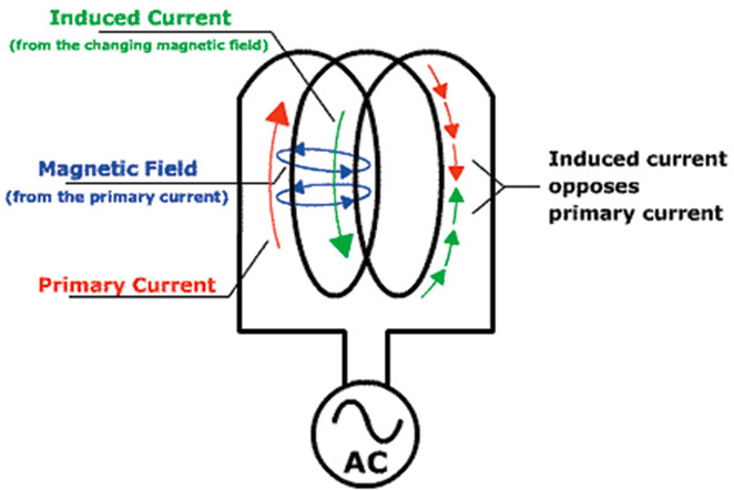 Figure 2 (Source: Collaboration for NDT Education)
Here we see primary current flowing clockwise in a coil. This flow gives rise to a magnetic field which induces a separate current that flows in the opposite direction. The result is similar to what would happen if traffic tried to flow in both directions on a one-way street.
Figure 3 shows the relationship of the current and voltage waves in a circuit that is purely inductive. These curves allow us to visualize, quantitatively, the effect the opposing current has on the flow of primary current in a coil or stator.
The result of this opposition causes the primary current to "lag" voltage by 90-deg (one full AC cycle is 360-deg). The importance of this lagging effect has to do with the resulting value of the volt-amp. The portions of the two curves that fall between the two vertical red lines illustrate this problem. In this area, the current curve is positive but the voltage curve is negative. Minus times plus equals minus and there is no such thing as a negative watt! So, this area provides no useful power.
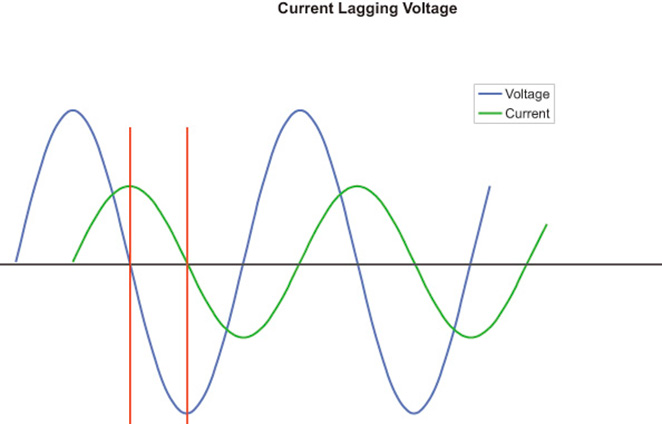 Figure 3
Even though it looks a bit complex, Figure 4 gives us an even better picture of what is actually happening. Here, my spreadsheet has multiplied voltage times amperage for each point on the X axis.
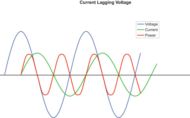 Figure 4
The result is the red curve which shows the actual power in the circuit. The portions of the red curve above the X axis represent the energy stored by the magnetic field, and those below represent that same energy as it is returned to the circuit. Since these portions have equal areas, the average power in the circuit is zero.
The numerical value of the power factor of a circuit depends upon the loads, and the effect those loads have upon the voltage and current in that circuit. In the case of a purely resistive load, voltage and current travel in sync (0-deg lag) and PF is 1. This value indicates that all of the power in the circuit is available to perform real work. In a purely inductive circuit, current lags voltage by 90-deg and its PF is 0. This value indicates that none of the power in the circuit is available to do work. All PF values between 1 and 0 are proportional to the lag of the current curve.
Because of the sinusoidal shape of the voltage and current curves the reduction in PF from 1 to 0 is not linear, but is a function of the cosine of the lag angle. In our resistive example, the cosine of 0-deg (lag) is 1 and in the inductive example the cosine of 90-deg (lag) is 0. If a circuit has a current lag of 45-deg, its PF is 0.707 (cosine 45) - not the 0.5 our analog brains would like it to be.
Now, as I said before, this unused power is not necessarily wasted. It is simply returned to the circuit. But, the fact that it is unused can have serious consequences for both consumers and providers of electrical power.
Next month we will take a look at a circuit with a more typical power factor. We will review the consequences of unused power and see how they impact both utilities and users. We will also take a look at what actually determines a particular motor's PF. We will end with a discussion of that other form of reactance and show how it can often provide a simple fix for low power factor caused by inductive reactance.
