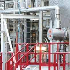
In most piping systems, particularly large diameter, swing check valves are installed (see Figure 1). They ensure that fluid in the system flows in one direction to prevent backflow that can cause contamination, stop over-pressurization events and act as a safety device to avoid the complete drainage of a piping system should a rupture occur.
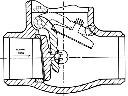
In normal operation, the disc inside the valve is lifted off its seat by fluid flow. When flow stops, the disc drops onto the valve seat, preventing reverse flow in the system. The shaft on which the disc is mounted is sealed on one end as it passes through the body of the valve, although some designs have a seal on both ends. The external portion of the shaft can be fitted with a counterweighted arm and/or a damper or an actuator, depending on the service requirement. This allows the user to monitor the position of the check valve, to facilitate smoother closure, to allow the user to force the valve open for pipe cleaning or to allow reverse flow under specific conditions.
Sealing Challenges
Sealing the shaft as it passes through the valve wall can be a challenge. The seals must be leak tight with rotary motion while minimizing frictional drag on the stem as it rotates. Valve designers should consider the packing friction at the design phase to ensure that the disc can close without exceeding the available force. Often, elastomeric seals are used in the stuffing box, but these are not usually considered an option at temperatures above 500 F (260 C). In elevated temperature applications, graphite-based seals are sometimes employed on the shaft.
Figure 1. Typical swing check valve. Image courtesy of Flowserve Corporation, all rights reserved.
.jpg)
Figure 2. Live loaded assembly
Case Study
Challenges can arise when modifications must be made to swing check valves. In one case, an end user had a swing check valve operating in steam at temperatures of 510 F (266 C) and higher than 750 psig (52 bar). During operation, turbulent flow in the valve caused radial shaft movement that was compounded by external counterweights mounted on the shaft. This caused increased wear on the packing and leakage from the stuffing box. Leakage became a chronic problem, requiring frequent adjustments to the packing gland (leakage was collected in buckets). This presented increased maintenance expense and potential safety concerns.
In an effort to reduce the shaft movement, the end user consulted the valve manufacturer and opted to remove the counterweights from the shaft and use a revised disc design. With this revised design, the effects of friction from the packing set became more critical. To ensure proper closure of the valve, a narrow window of allowable friction had to be maintained, with no leakage. If friction from the packing was too high, the check valve would not close when required.
The end user then contacted the compression packing supplier to investigate the available options to improve performance. An open discussion was initiated to clarify the application criteria and expectations and to ensure that the data on the stuffing box and current solution were accurate. After a brainstorming session, key requirements were identified:
- Packing consolidation must be minimized. The intent was to ensure that the packing did not require frequent adjustments and that the gland nose did not bottom out in the stuffing box over its service life.
- Gland load on the packing set had to be maintained for as long as possible.
- Packing friction must be minimized to ensure correct valve operation.
The Solution
Given the high operating temperature and other considerations related to purity, a graphite-based packing solution was selected. A standard five-ring set was used, along with a spacer bushing to reduce the stuffing box depth. This reduction decreased the contact area of the packing with the shaft from the previous arrangement, which resulted in a more effective seal with less packing consolidation.
The primary sealing rings were die-formed, flexible graphite tape made to a specific, controlled density. In place of typical, braided carbon-fiber-based anti-extrusion rings, a die-formed, braided, flexible graphite end ring reinforced with austenitic nickel, chromium-based wire was substituted. To minimize the consolidation, the end ring was die-formed with a larger cross section and compressed to a high density.
To maintain gland load on the packing set over time, a live-load spring assembly was engineered for retrofit into the valve that provided the maximum compensation for the anticipated packing wear and consolidation (see Figure 2).
The disc springs store applied force, and as the packing wears and consolidates, the gland stress can be kept more constant with few, if any, adjustments. Because of the horizontal shaft orientation, keeping the springs concentric with the gland bolts was important so that they did not hang up on the bolt threads. Live-load designs are available for this. In this application, an external alignment type was chosen.
The correct load for the packing had to be determined using a combination of experience and experimentation. The live-load assembly was designed for a range of loads, with its mid-compression point the target load. The available travel was set at the maximum possible. This may have resulted in a larger, more expensive live-load arrangement than would be found on a typical gate or globe valve, but the user was clear that this solution had to provide four and a half years of leak-free service.
An installation procedure was developed to apply the gland bolt torque in increments, starting with the minimum value designed for the assembly. The valve was pressurized and checked for operability and leakage. If any leakage was detected, the gland bolt torque was increased slightly, and the test was repeated until the seal was achieved and the disc was still free to move as required. To date, the application has been running for three, leak-free years.
Summary
For difficult applications with special challenges, collaboration can be important. In this case, an end user’s experience and understanding of the application history and challenges and the compression packing supplier’s knowledge and experience with sealing options resulted in a successful, unusual sealing solution. Communication and open discussion are critical. Each party’s expectations were clearly laid out before any specifications were drafted or purchases made. If end users have a challenging sealing problem, they should contact and collaborate with their sealing solution provider. P&S
Next Month: How does lubrication affect fastener torque & resultant tension?
We invite your suggestions for article topics as well as questions on sealing issues so we can better respond to the needs of the industry. Please direct your suggestions and questions to sealingsensequestions@fluidsealing.com.