Editor's Note: This article is part of an ongoing feature series. For more "Sealing Sense" articles, click here.
How do variable speed drives impact mechanical seals?
This month’s “Sealing Sense” was prepared by FSA member Henri Azibert.
The use of variable speed drives (VSD) has become increasingly more prevalent in an effort to improve the energy efficiency of pumping systems. Efficiency is improved through the ability of the VSD to adjust the rotational speed of a rotodynamic pump and match its hydraulic characteristics to those of the system in which it operates.
Whether the mismatch was due to the variation in required pump output or incorrect sizing of the pump, there is no question that the ability to easily vary pump speed has been a major advance in the overall performance of a pumping system. This has increased the energy efficiency, as well as the reliability of the equipment. Problems—such as cavitation or shaft deflection—can be alleviated by running the pump at optimal system speed. But how do VSDs affect mechanical seals?
How Are Seals Affected?
One of the impacts of variable operating speed that is rarely considered is the effect that it may have on the mechanical seal. Mechanical seals are affected by many factors. These include:
- Fluid properties
- Process temperature
- Primarily, the pressure and peripheral velocity of the sliding seal surfaces
Varying the pump speed will have an effect on these factors. Although the fluid properties and the temperature of the fluid is not likely to change significantly with rotational speed, the pressure most likely will change, and the sliding velocity definitely will.
Seal Face Reaction
The effectiveness and reliability of the seal is to a large extent controlled by the seal faces. In some traditional designs, the forgiving wear characteristics of a carbon-graphite seal face were relied upon to adjust to a profile that would promote a stable lubrication regime. Changing conditions, such as start-up after a period of stand-by, would result in either leakage or wear until steady operating conditions were reached.
Mechanical seal faces are subject to pressure and temperature gradient induced distortions. As the pressure and speed change, these distortions also change. The primary effect with varying speed is heat-induced distortion because the heat generation is directly proportional to the speed, while seal cavity pressure remains close to suction pressure for many pump designs.
Therefore, changes in speed will most likely result in changes in face profile, which can then result in wear. Most modern mechanical seal designs are fairly insensitive to variations in pressure and speed. Pressure and speed are interrelated. For outside pressurized seals, the distortions induced by speed and pressure tend to counteract each other. For most applications, the effect of variable speed in pumps can be ignored. In some areas, however, the variation in speed should be reviewed because it can negatively impact mechanical seal life. Setting aside problems that might otherwise affect pump reliability, the mechanical seal environment control system could be substantially affected in some situations.
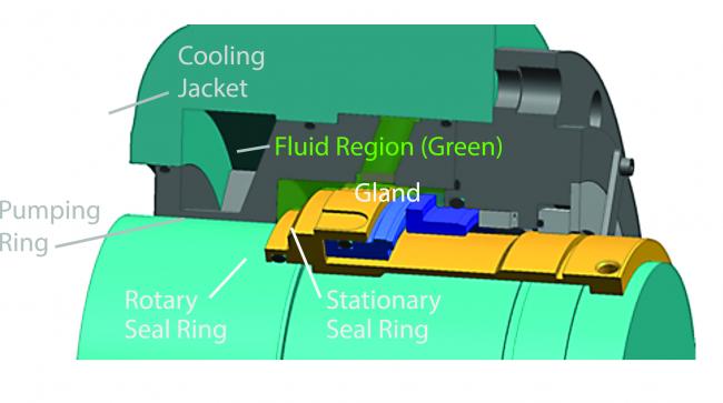 |
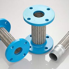
| Figure 1. API Plan 23 sealing system with cooling jacket |
Control of the Seal Environment
This discussion can begin with API Plan 11, which is used to recirculate liquid from the discharge of the pump, typically through an orifice, to the seal cavity. This recirculation is usually directed to either maintain a specific pressure in the seal cavity for low vapor pressure fluids or to remove heat generated from the seal. The flow is a function of the pressure differential between discharge and seal cavity pressure. The heat generated from the seal is directly proportional to the speed, but the pressure is proportional to the square of the speed change.
Therefore, the pressure may be too low for a necessary vapor pressure margin, or the flow could be too little to properly remove seal generated heat especially at lower speeds. The system should be sized so that the proper vapor pressure margin or flow rate is achieved under the maximum and minimum conditions. Without this determination, certain operating speeds could affect seal life or increase emission levels.
API Plan 11
Two variations of Plan 11 are Plan 21 and Plan 31. In Plan 21, a line from discharge is routed through a heat exchanger to the seal cavity. This is used for a hot process to cool the seal. By reducing the speed, the pressure differential driving the flow through the heat exchanger will decrease, and the temperature at the seal will increase.
The heat exchanger and piping system must be designed to reduce the process temperature sufficiently under the extreme conditions. Just adding a VSD without resizing the system could result in elastomer or face damage.
In the case of API Plan 31, a cyclone separator is used to bring clean fluid to the seal cavity using the pressure differential between discharge and suction. The efficiency of these devices is closely tied to the differences in pressure between discharge, seal cavity and suction. As these pressures differ, so will the ability of the separator to feed clean fluid to the seal.
Circulating Devices
End users should also be careful in situations in which a circulating device built into the mechanical seal is used to drive fluid through a heat dissipating external device. This external device can be a heat exchanger or a reservoir depending on whether the user installs API Plan 23 (single seal circulating fluid through a heat exchanger) or Plan 52/53 (dual seal circulating a buffer or barrier fluid through a reservoir, which can also include a heat exchanger).
When these plans are used simply to handle the seal generated heat, there is likely to be little impact. Because the flow rate of the pumping device and the heat generated by the seal are proportional to the pump speed, the decrease in flow rate is compensated by the decrease in heat generation. However, when these plans are also used to cool the seal environment because of high process temperatures, the decrease in speed results in elevated seal temperatures that can adversely affect seal life and operation. In these circumstances, the lowest speed is the most critical case that needs attention.
Severe-Duty Applications
Finally, severe-duty applications may also require special considerations. When the pressure, temperature and speed are elevated, a custom design with rigorous analysis might be required. For example, a boiler feed water application has the original conditions of 5,500 rpm, 170-millimeter shaft, seal face velocity over 11,000 feet per minute, (56 meters per second), and 190 psig (13 bar), with a process temperature of 350 F, (175 C). Figure 1 is a cross-sectional view of the sealing system used in the application.
A standard design was used and verified to be able to handle these conditions. FEA analysis predicted a convergent profile to promote face lubrication. The operation then changed from a constant speed of 5,500 rpm to vary from 5,500 rpm to 3,300 rpm on a daily basis. Analysis of the same geometry at 3,300 rpm showed that the seal did not have an optimal face profile at the reduced speed with a slightly divergent profile. Both profiles of this original design are shown in Figure 2.
Although the seal could operate under this regime, an optimized face geometry was developed to handle both conditions (see Figure 3). Note also the reduced temperature under both regimes.
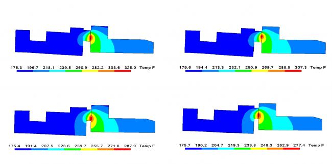 |
| Figure 2. (top) FEA analysis — standard design; Figure 3. (bottom) FEA analysis — optimized design |
Pumping Ring Efficiency
Finally, consideration must be given to the efficiency of the pumping ring. The role of the pumping ring is to circulate fluid to a heat exchanger to dissipate heat generated from the seal faces and to cool the process fluid in the seal cavity that is constantly heated from the heat soak. At the lower speed, enough circulated must be present to bring the temperature down to the desired level. However, at high speeds, there can be cavitation problems if the design of the pumping ring is too aggressive. Achieving a balance can be challenging and may require flow analysis (see Figure 4).
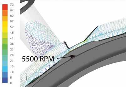 |
| Figure 4. Flow velocity vectors at the exit of pumping ring |
Consider the Seals
VSDs significantly improve pump efficiency, but their potential impact on mechanical seals must be recognized and considered. While in most cases varying the speed of the pump will have no adverse effect on the mechanical seal, certain situations require careful analysis. These are primarily cases in which environmental controls are used with the mechanical seal. The purpose of these controls must be well understood so that the system design can properly function under the varying operating conditions produced by variable speed drives.
Next Month: What are the current industry best practices for the assembly of bolted flange connections?
We invite your questions on sealing issues and will provide best effort answers based on FSA publications. Please direct your questions to: sealingsensequestions@fluidsealing.com.