

Transport of hydrocarbons in pipelines has a long tradition and has been applied for decades all over the world. Millions of miles of pipelines serve as conduits for the distribution of natural gas and refined products midstream and upstream, as well as the transport of crude oil and produced gas from the producing fields to processing in refineries and gas plants or for storage in tank terminals and inground caverns. Pipeline transport is a safe, energy efficient and unintrusive way of transporting hydrocarbons from one point to another, despite its vulnerability to leaks or ruptures.
This article will focus on simultaneous transportation of multiple phases of produced fluids including oil, water, wax and emulsions together with associated gas. Traditionally, each phase is conveyed as single-phase flow in individual flowlines, mostly one for each phase. As new pump technologies are being developed for pressure boosting, more interest has been shown for combining the gas phase with the liquid phases in a commingled flow stream using a single pipeline—also for multiphase transport across longer distances and with varying topographic conditions.
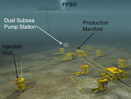
The concept of a single multiphase flow line has, until now, mostly been applied in subsea environments where the producing wells of a drill center on the sea floor are tied back to surface processing on a floating production, storage and offloading (FPSO) platform. The tie-back distances can be long and challenging for flow assurance and pressure boosting in deeper water with lower surrounding water temperatures. To make long tiebacks possible when using a single flow line, subsea multiphase booster pumps are often installed in manifolds close to the producing wells on the sea floor.
These pumps not only bring the production to the surface but also successfully support the natural reservoir pressure of the formation to increase and extend oil and gas production.
This concept and mode of operation is also applied in onshore oil and gas production using conventional pipelines where similar flowing dynamic conditions can apply, as in a subsea pipeline. When it comes to supporting the use of a single flow line for multiphase transport, it is important to address the pump principle and design to create the necessary pressure boosting and flow assurance.
The combination of different fluids with varying densities and viscosities together with gas results in an interchangeable flow regime, which the multiphase booster pump must be able to handle without gas locking as a result of liquid starving. Additionally, slugging or surging from terrain and topographical variations can create challenging conditions, and wax and solids precipitations can also result in startup and operating difficulties. Other concerns include non-Newtonian emulsions from changing oil/water ratios over time, hydrate formation in cold weather and keeping flowing temperature within pipeline specifications.
Some commonly used methods to address these flowing concerns are injecting diluents, mono ethylene glycol (MEG) and various chemical additives of all kinds including surfactants, as well as adding heat to the pumped liquids via jacketing and dual-walled pipes and insulation.
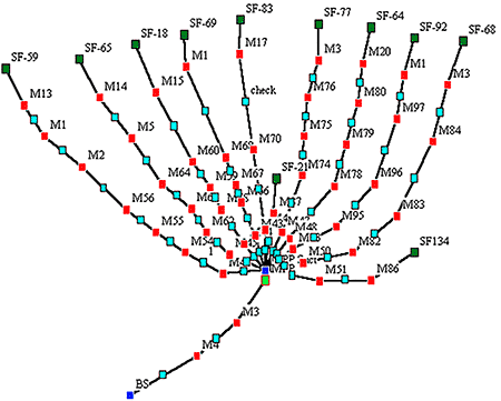
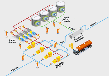
An example of a multiphase pipeline is shown in Image 2. The multiphase pump will do two things. First, by lowering back pressure in the gathering lines, the production is increased. Second, by boosting the commingled flow in a single multiphase pipeline, phase separation and processing can be removed from the producing field.
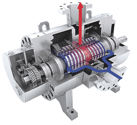
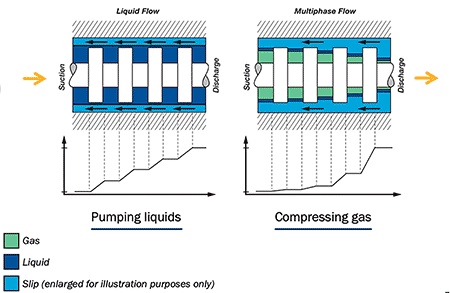
A twin-screw multiphase pump can pressurize liquids and gas in any combination without separation or phase split, as shown in Image 4. The liquid that is needed for sealing the screws and to remove the heat of gas compression comes from the process and is circulated back to the pump from a downstream liquid knock-out boot. The gas is compressed by the internal liquid slipstream traveling in the clearances between rotors and liner, allowing the pump to go from 100% gas to 100% liquids in an instant. Low internal velocities and the absence of pulsations result in low stress to shear-sensitive liquids.
In midstream pipeline applications, the twin-screw pumps are often used in trunk or lateral pipelines for heavy crude oil/bitumen. The pump’s ability to handle gas slugs when diluent, condensate or light hydrocarbons are injected is a benefit to prevent upsets from gas breakout in suction lines with inadequate net positive suction head available (NPSHa). In such applications, the twin-screw pump—thanks to its gas handling capability—can run uninterrupted and pressure boost despite gas or vapor flashing.
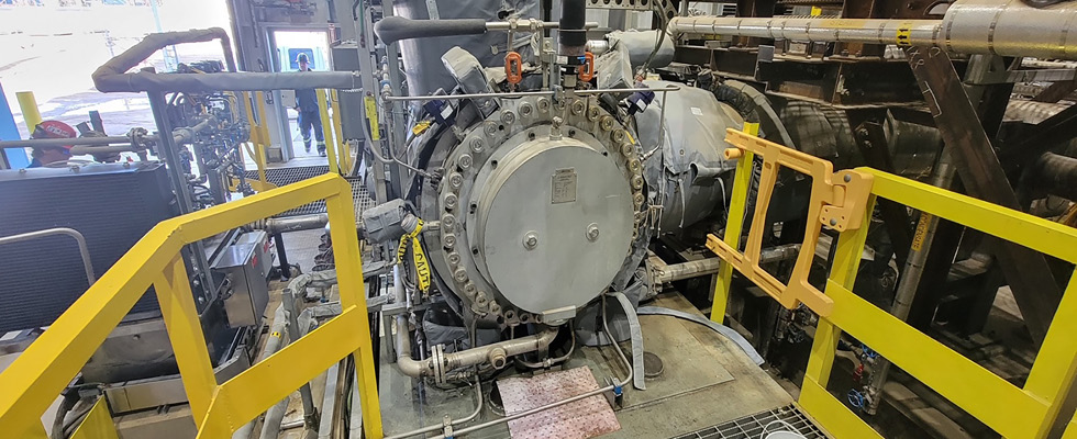
Image 5 shows an example of a 2,800 horsepower (hp) twin-screw pump serving a Canadian 24-inch, 60 miles long heated and diluent injected heavy oil trunk line. Another advantage is its ability to start up a shut-in line using variable speed control to slowly build up flow while maintaining full discharge pressure.
In high capacity and long pipelines, a slug catcher or inlet separator upstream of the multiphase pump can be applied. It will help to knock out a more stable liquid condition in case of very long gas slugs, as the multiphase pump requires a minimum of 3% to 5% liquid supply at inlet conditions. To inject the liquid in the multiphase pump, a separate, smaller liquid pump is used. In a previous subsea multiphase pumping testing facility, the twin-screw pump proved stable performance also with a heavy slug flow via the use of continuous liquid injection.
The future use of larger multiphase pipelines is likely to expand, as more centralized processing is expected to be used. Besides the scale effect advantages from larger operations, which are bringing lower facility, capital and operating costs, the environmental aspects are increasingly important. With central processing away from the producing fields, better control of voluntary or involuntary flaring is possible, as is fugitive emission control. Pumping stations for multiphase pipelines are presently on the drawing board and may look like the illustration in Image 6.
Thorough computational fluid dynamics (CFD) analysis of the upstream pipeline of the multiphase pumping station is needed to determine the nature of the flow regime, slug length, slug speed and frequency to size the slug catcher or inlet separator correctly. Topographical considerations can make it difficult to define the expected flow regime at the arrival pumping station. An example from the past has been river crossings where the low point adds to slug intensity and slug length.
In one study, a pipeline operator was concerned about frequent theft from single phase pipelines and found a multiphase pipeline would discourage such activities.
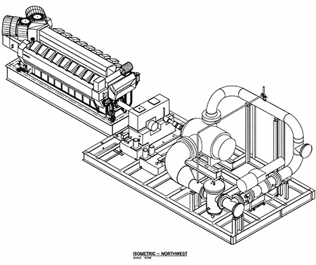
In remote areas, natural gas or diesel fueled engines for driving the multiphase pump can be used. Image 7 shows an illustration of how a larger diesel engine-driven pump skid could be featured.
