
First of Two Parts
07/09/2015
Users have several options for controlling piping systems. Previous columns established that every piping system is composed of pump elements, process elements and control elements. This column will focus on the control elements, which improve the quality of the product. Control elements can be either passive or active.
The System
The example system is a water supply system in an industrial plant. The system includes a supply tank, which provides a constant source of fluid to the pump. The system flow demand to the plant ranges from 200 to 500 gallons per minute (gpm) with an average system flow demand of 400 gpm. The pump was sized so the flow rate exceeds the maximum expected system flow demand of 500 gpm. The process fluid is pumped to the destination tank. The elevation of the tank provides the head at sufficient fluid quantity to all plant loads. This column will consider the different types of controls found in the piping system and explain the advantages and disadvantages of each type. All the examples presented deal with maintaining a level in a tank, but the same controls can be applied to different process variables (see Figure 1).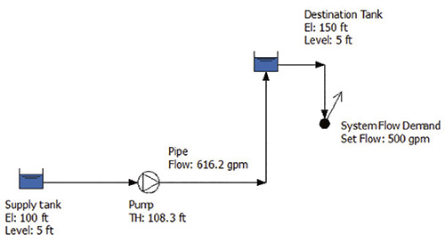 Figure 1. The example system shows how control interacts with the system. The system provides sufficient flow to the destination tank to supply a maximum of 500 gpm flow rate to the system. The purpose of the control is to have the system supply the flow needed by the process. (Graphics courtesy of the author)
Passive Controls
Passive controls are the most basic. Examples include overflow, bypass, on/off and manual throttling. These controls activate when a process variable is reached and a single action occurs limiting the variable.Overflow & Bypass Control
One way to handle the excess capacity of the pump is to direct excess flow back to the supply tank. Using this approach, the fluid keeps the destination tank full, and all excess flow beyond the system demand is directed back to the supply tank. This approach provides a fairly constant pump head value, resulting in a fairly constant flow rate. This can be either an advantage or disadvantage depending on where the pump is operating in relation to its best efficiency point. The advantage of this method of control is initial costs. It only requires a recirculation pipeline and a tank overflow. The disadvantage of this method is that the excess flow must be pumped to the destination tank (the difference between the pump flow, less the process demand). This creates increased pumping costs, with a resulting energy loss based on the quantity of the return flow. Table 1 shows the energy balance sheet for the annual flow rate of 400 gpm.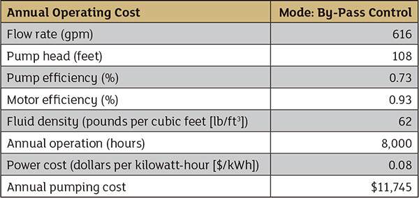 Table 1. Annual operating cost using overflow control. The system requires an average flow rate of 400 gpm, but 616 gpm is pumped to the destination tank.
On/Off Control
Another way to handle excess pump capacity is to turn the pump off when the liquid level in the destination tank reaches a predetermined high level. When the pump is off, fluid stops flowing into the destination tank, but the system flow demand continues. The outflow from the destination tank causes the tank level to decrease. At a predetermined low tank level, the pump starts. Because the pump capacity is greater than the system flow demand, the tank will fill over time until the high tank level causes the pump to stop. The cycle repeats as necessary. The advantages of on/off control are simple design and low cost. A level switch in the destination tank turns the pump off with a high tank level and turns on when the tank level is low. One disadvantage of this method is that a single tank level is not maintained. The level varies between the high and low levels. Also, the pump is cycled on and off, resulting in increased wear on the pump and motor. Increasing the capacity of the destination tank minimizes the number of pump starts per year but increases the cost of the pump system.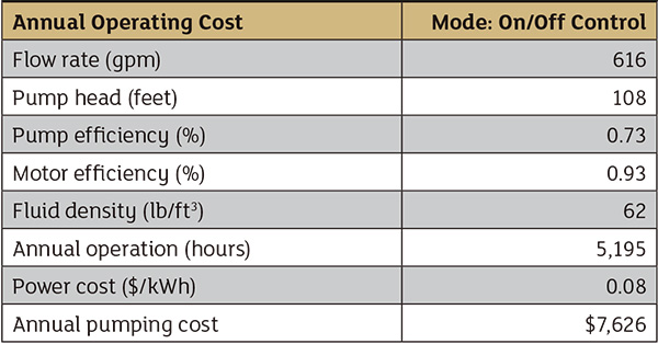 Table 2. The annual operating costs for the on/off control. The flow rate through the system is the same, but the pump is only run 5,195 hours per year.
Manual Control
A third way to handle the excess pump capacity is to install a throttle valve on the pump discharge and have an operator manually limit the flow rate to the destination tank. When an operator adjusts the valve hand wheel to the closed position, the head loss across the valve increases, causing the pump to run back further on its pump curve. This results in a reduction in the flow rate to the tank. To increase the flow rate, the valve is opened, reducing the head loss across the valve and causing the flow rate of the pump to increase. The closer the flow rate through the throttle valve is to the system flow the slower the change in tank level. This process is successful when the operator can maintain this tank level in the normal course of their duty. A tank overflow should be provided to handle unexpected rapid changes in tank levels or inattention by the operator. The advantage of this approach is low initial cost, provided the operator can maintain the tank level without excessive attention. The disadvantage is the possible variability in the tank level and inadvertent loss of process fluid.
Next month's column will detail active controls options.
