These valves can alleviate a variety of pump system issues.
Singer Valve

Pipe bursts due to transients and surges are common. Not only are the maintenance costs of these repairs high, but when adding possible litigation for third party damages combined with the potential cost of water loss, another pipe burst can have big consequences.

Surges, or transients, are the result of a rapid change in liquid mass velocity within a pipeline. This kinetic energy, released as pressure, acts to expand the pipe diameter and can destroy fittings, pipes, valves, instrumentation and pumps. Pressure waves travel the length of the pipeline of the offending device, then reverse direction. The waves move at a constant speed until they meet a barrier. The reflected and incident waves may superimpose each other to produce a more compounded wave pattern that includes double peaks and double troughs. The consequence of improper protection from surges or transients could be a pipe burst or equipment failure and result in damage, water loss or litigation.

Transients, surges and the resulting pipe bursts can be caused by numerous events: loss of power at a pump station, pump station programmable logic controller (PLC) malfunction, single-speed pump motors without adequate pump control valves or the rapid closure of isolation valves.

pressure relief valves
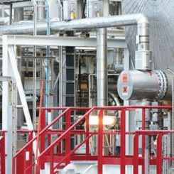
Image 1. Pressure relief valves, installation schematic and application (Images and graphics courtesy of Singer Valve)

The selection and sizing of pressure relief valves is very important to protect pipelines, piping equipment and pumps. The application and selection of relief valves may require a detailed analysis by a transient specialist who looks at all factors before making an informed choice. Pressure relief valves do not have to be limited to pump stations and can be strategically located anywhere in the distribution system to deal with overpressures and transients. The pressure relief valve is normally mounted off a tee on the header or mainline and opens under high pressure to discharge the relief flow to atmosphere or other suitable low-pressure zone.

It is important to consider the discharge that is released from the relief valves when they react to the overpressure. The discharge can often be chlorinated, which poses a threat for fish-bearing streams, landscaping, etc. A well-considered approach to the proper management of the discharged relief water is always required.

A good initial guideline for sizing a relief valve is to base the flow rate capacity of the valve at 25 percent of the maximum flow in the main pipeline. It is important that the relief valve be sized so as not to be too small or too large. An undersized relief valve will not have enough capacity to relieve the overpressure while an oversized valve will result in excessive flow and possibly a non-recoverable pressure loss.

Pressure relief valves are typically used where there is a risk to the system of higher pressure occurring, and frequently used in systems that have pumps. Their selection and sizing is determined on whether a simple over pressure protection is required, or if there is risk of transients, in which case a surge anticipating relief valve may be selected. 

Pressure Relief Valves

A diaphragm actuated, hydraulic pilot operated pressure relief valve responds to opening only when a system is over pressured, typically 10 to 15 percent over the normal operating pressure. If an overpressure or surge pressure occurs, the relief valve opens quickly to dissipate the surge by discharging water to atmosphere. When the system pressure has stabilized, recovering below the surge pressure, the pressure relief valve closes at a controlled rate and normal operation of the system resumes. Rapid or uncontrolled closure of a relief valve may result in secondary surges in the system. Closure rate should not be too fast to create closing surges and not too slow to result in excessive relief water loss.

Surge Anticipating Relief Valves

Standard or single pilot relief valves only open when the system pressure exceeds the relief pilot setting. In a pumping system, where an unexpected pump shutdown occurs, the mass velocity of the water moving away from the pump will initially create an excessively low pressure within the pumping system. This low pressure surge wave will occur prior to an eventual returning high pressure surge wave. The time to open and the capacity of the relief valve opening under this resultant high surge may not be sufficient to adequately dissipate the system surge, resulting in additional and repeated surge waves created within the system. The time, frequency and severity of these waves may become catastrophic and end in a pipe burst or other system failure, even in system where a relief valve was installed and satisfactorily sized. Having the ability to anticipate a surge event would allow the valve to respond and open more quickly and effectively to a surge event.

surge anticipating relief valves
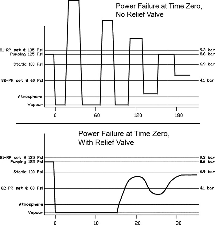
Figure 1. Depicting effectiveness of surge anticipating relief valves

A dual pilot relief valve, with the addition of a low surge pilot, anticipates the impending high return surge by opening the relief valve upon sensing a low pressure surge. This low surge pilot allows the valve to open and relieve a greater capacity to minimize the surges below a critical level and of shorter duration. The high surge pilot will function normally to allow the relief valve to open fully on high surge pressure, but operating from an already partially open relief valve. Surge anticipating relief valves need significant static pressure to operate properly. A minimum of 43 pounds per square inch (psi) is typical.

surge anticipating relief valves
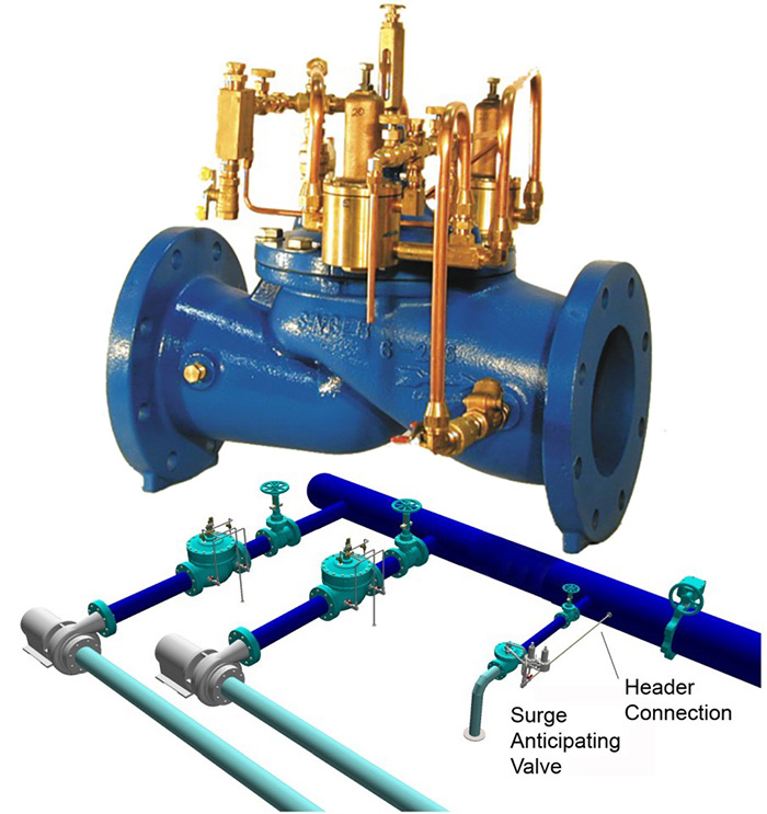
Image 2. Surge anticipating relief valve and installation schematic

The low surge pilot is typically set at approximately 60 percent of the static system pressure, sufficiently below the system operating pressure. The setting of this pilot is critical, as is the capacity and sizing of the valve. It is imperative that upon operation of this surge-anticipating relief valve that system pressure can recover above this low surge pilot set point so that the valve may close and allow normal operation of the system to resume. If this low surge pilot is set too low or the valve is sized too large, excessive relief flow volume will prevent the system pressure from recovering, since the low surge pilot will not close and so the relief valve will not close, resulting in a complete loss of system pressure and excessive water loss.

Since many relief valves, including surge anticipating relief valves, are often oversized, valves are frequently specified with valve devices designed to limit or restrict the lift or opening under low surge pilot operation. Limiting the valve travel under low surge pilot relief acts to promote the system pressure to recover above the low surge pilot and allow the valve to more reliably close when the surge waves have been dissipated through the open relief valve. These devices are referred to as hydraulic flow limiters (HFL). These provide a compromise to allow the surge anticipating relief valve to be oversized for high pressure relief capacity, yet allow for reliable valve closure under low pressure relief.

Bigger is not necessarily better when it comes to surge anticipating relief valves. It is also very important that the sensing line is connected directly from the header and not from the valve body port, to ensure accurate header pressure sensing. Surge anticipating relief valves act as an insurance policy by allowing the valve to start opening before a peak on the transient returns. Surge anticipating relief valves are often a good selection when design criteria calls for valves six inches or larger. Surge anticipating relief valves can be easily tested, and their operation can be replicated in a static condition in the field.

Electrically Timed Closure After Power Failure

This valve is similar to the surge anticipating relief valve, with the exception that the low pressure pilot is replaced with a solenoid valve. All other sizing protocol and design criteria remain the same. No static pressure is required as the valve closes on a timer. The valve opens because of either power loss or by way of the high pressure pilot. If power loss is the major concern, then this style of valve can be an excellent selection. Timing for the solenoid to close is normally coordinated with the critical period—the time it takes for the surge return. Always consult with a transient specialist for sizing and selection concerns.

electrically timed valve 
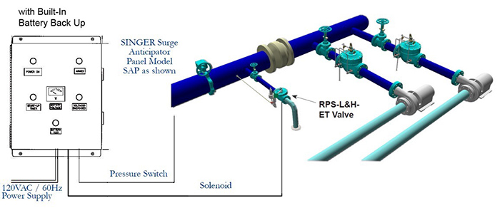
Image 3. Electrically timed surge anticipating valve

The decision to use, or not to use, surge anticipating relief valves is often based on the perceived complexity of these valves. Having multiple pilots with satisfactory set points, often applied with hydraulic flow limiters and requiring adjustment, along with warnings and dangers of undersized and oversized valves, surge anticipating valves are often misunderstood and overlooked as part of the surge protection in a pump system design.

Rate of Rise Relief Valve

Surge anticipating valves based on the detection of a system pressure abnormality leads to another surge anticipating valve model, the rate of rise relief valve. Valve opening pressure relief on a rapid pressure rise system, even before a high pressure relief setting is reached, anticipates a surge event to allow the valve to respond and open more quickly and efficiently to a surge event.

Rate of rise relief valves add another safety feature to standard relief valves. The valves open when they detect a sudden change in pressure.

rate of rise
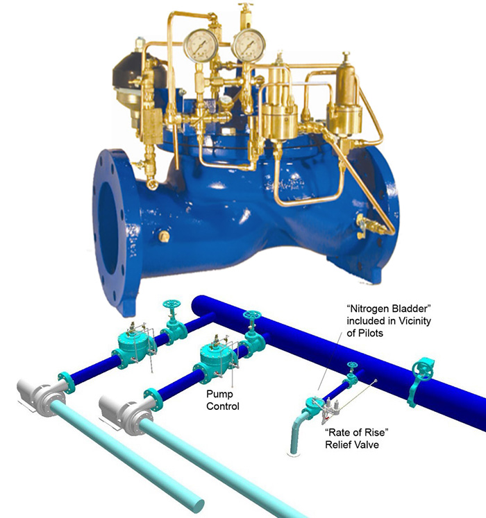
Image 4. Rate of rise relief valve and installation schematic

On power failure, and after the low pressure interval, the returning wave starts building pressure. The rate of rise pilot senses this rapid increase and immediately opens. This rate of rise surge pilot allows the valve to open, even if only partially, to relieve a greater capacity of the returning surge to minimize the surge below a critical level and of shorter duration. Also equipped with a high surge relief pilot, this pilot will also open fully to ensure the relief valve opens fully, on high surge pressure, but operating from an already partially open relief valve.

This valve model is very attractive, as equipped with a pre-charged accumulator, the valve has positive pressure to force the pilot to open and close. It removes the risk of failure to close, should the pressure not recover. Downstream static pressure is not required for this valve to operate effectively, so downstream elevation is not required.

Another major advantage of the rate of rise relief valve is that sizing is not critical. If the valve is oversized, it will recover and close on conclusion of the transient. It is still recommended that the valve be sized based on roughly 25 percent of the mainline flow rate. The rate of rise relief valve starts opening immediately when pressure begins to rapidly rise. It uses a nitrogen bladder accumulator for very accurate sensing of pressure rise.

The source of surging is most commonly initiated by the routine starting and stopping of pumps within a pump system. Minimizing the system surges on pump start and stop cycles can vastly improve the health of a pump system by using inline or bypass pump control valves, which slowly open and close to gradually increase or decrease flow into the mainline.

Booster Pump (Inline) Control

Booster pump control (BPC) valves are located in line, downstream of the pump. When started, the pumps start against a closed valve. The solenoid is then energized, opening the BPC. At pump shutdown, the solenoid valve is de-energized by the system control to put the valve into closing mode.

inline control valvesImage 5. Booster pump inline control valves, installation schematic

There is an electronic limit switch on the stem of the BPC, so when the valve is almost fully closed, a signal goes back to the pump control panel to shut the pump down. The opening and closing speeds are adjustable. This is a very efficient way to manage pump control and does not require any static pressure in the piping system downstream. When sizing BPC valves, consultants often prefer to oversize the valves to minimize pressure loss through the valves.

The dilemma is that when selecting pumps, efficiency is always a concern. When a BPC valve is used, if sized too small, pressure loss or lack of efficiency may be affected.

Deep Well (Bypass) Pump Control

If site conditions permit, deep well (DW) pump control valve solutions can be a very economical and practical solution to pump control. This type of valve requires some static pressure downstream to work effectively. Elevations are the best method to ensure the static condition, which should be a minimum of 100 feet. This static pressure applies pressure to an inline check valve until pump pressure overcomes this check valve and allows flow into the distribution pipe.

DW pump control valves
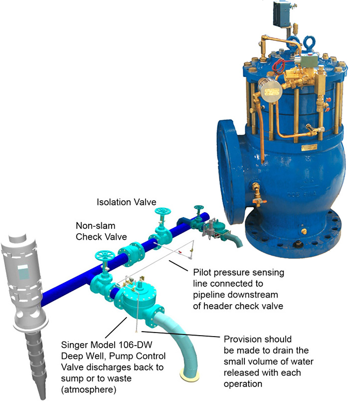
Image 6. DW pump control valves and installation schematic

The pump starts against a fully open DW valve. This valve is located off a tee and discharges to atmosphere. When the pump starts, a signal is sent to the solenoid on the DW valve, which starts the closing process of the valve. The speed of closure can be selected by adjustments to the manual needle valve. As the pressure builds in the manifold, it eventually overcomes the static pressure holding the check valve closed and water commences flowing to the system. At pump shut down, the solenoid on the DW valve is de-energized, which causes the valve to start opening. The opening speed can be manually adjusted using the needle valves.

When the valve is almost fully open, a limit switch, mounted on the stem of the DW valve, sends a signal to the pump control panel to shut the pump down. If site conditions are correct, this can be a very efficient way of managing pump control for single-speed motors.