Variable Flow Pumping for Hydronic Heating & Cooling
Operators can increase efficiency with packaged HVAC pump systems, inline multistage pumps, and advanced motors and controls.
Grundfos

Before talking about pumps, take a look at another piece of equipment used to maintain comfort in a building: chillers. A chiller consists of a compressor, condenser, evaporator, expansion valve, power and controls unit, and many other ancillary items. When chillers were first introduced to the market, they were supplied as separate components, bringing many challenges during installation and commissioning. This is why manufacturers started manufacturing chillers as complete packages.

Why should pump systems be any different? Pumping systems are comprised of pumps, motors, isolation valves, check valves, a power and control unit, and other ancillary items such as gauges and sensors. One could argue that pumps should be supplied as packages for the same reasons as chillers and boilers.

HVAC Design Requirements & Pumping Guidelines

The principal role of the pumping system is simple: provide enough flow so the building can be adequately heated or cooled. The pumping capacity, namely flow and head, is determined based on the building’s peak demand requirements. Since the building will rarely reach these peak design requirements—or if it does, it is only for a short period—the pumping system should be optimized for part-load conditions. Today, the most common approach to ensure good pumping efficiency at part load is the use of variable frequency drives (VFDs). The increased use of variable speed is also being driven by the building construction codes, which now include energy.

The American Society of Heating and Air-Conditioning Engineers (ASHRAE) has included hydronic variable flow pumps in the Energy Standard for Buildings (ANSI/ASHRAE/IES 90.1, section 6.5.4.2). This section of the code requires pumps to have controls that will result in pump motor demand of no more than 30 percent of design wattage at 50 percent of design water flow.

NEMA Premium
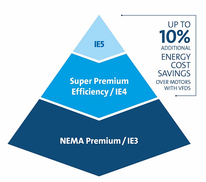
Image 1. Cost savings on NEMA Premium motors (Tables & images courtesy of Grundfos)

HVAC Pumping Design Practices

A common approach is to select one pump to handle the total flow and specify a second pump as a backup, resulting in what is considered “100 percent redundancy.” With the use of VFDs, this has been an acceptable approach and, in most cases, can meet the building energy code requirements.

When looking at actual building cooling or heating requirements, this can result in pumps operating at below 20 percent of the rated capacity, and even with variable speed drive (VSD) control this can result in less than optimum pumping efficiency.

Engineers should look at actual cooling and heating water demands over time when selecting which pump configuration to go with. This can result in multiple smaller pumps being more efficient than larger counterparts. Software can help determine building loads, which can help calculate flow rate data for each hour of the day for a full year. This information can be summarized to help select the optimal number of pumps. Table 1 shows the chilled water flow demand for a variable flow system.

chilled water
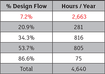
Table 1. Chilled water demand based on building cooling loads

If chilled water flow peak demand was 1,000 gallons per minute (gpm), this pumping system would be operating at around 72 gpm for over half of the pump system’s duty cycle. This low flow demand brings up questions when considering pump selection. Is this below the pump’s preferred operating region (POR)? And more importantly, is it below the pump’s allowable operating region (AOR)? What is the pump efficiency at this low flow range? Is this flow below the chiller’s minimum flow capacity? Would it be better to use three or four smaller pumps coupled in parallel?

When multiple pumps are to be considered, this is where providing them as a package can be beneficial.

Field-Built Multipump Systems

Specifying pumps is more than addressing hydraulic considerations. Specifications must include motors, drives, controls, valves and any other equipment necessary for the successful installation and operation of the pump system.

Engineers and building operators need the assurance that the pumps, motors and drives will work in harmony for many years. What sets the stage for this is proper installation—which requires planning—and that starts in the design phase. See Table 2 on page 67 for design phase considerations.

design phase
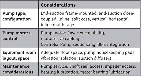
Table 2. Design phase considerations

Users should examine the details closely for the multipump field-assembled system to be designed, purchased, installed and commissioned successfully. It is common for a miscommunication and/or details to be left out. Examples include: motors need to be 208 volt, but controls and drives were ordered at 460 volt; a missing gauge here, a sensor there; where a sensor should be located along with drive and control settings; the wrong type of valve; and so on. Oversights like these can delay the installation and commissioning process.

Multipump Packaged Pumping Systems

Looking back at the chiller example, it should be clearer why a packaged system can be a good idea.

A packaged system supplier normally has complete specification packages that cover all the included equipment, such as pumps, motors, drives, controls, valves, and other ancillary items such as sensors and gauges. If the project has special requirements, the engineer can modify a standard specification into something more specific.

HVAC Pumping: Pump Types

One decision engineers face is the type of pump to specify. The most common type of pumps found in hydronic heating and cooling applications are end-suction pumps.

They are relatively inexpensive and offer pumping efficiency at the rated condition, making them a practical choice for this application.

Inline vertical multistage pumps have been under-used in these applications. This is commonly used in more demanding applications such as boiler feed systems for steam generating plants and pressure boosting systems for multistory buildings. The modern version of this pump has been used since the late 1970s and has grown in size and versatility.

Vertical multistage pumps have flow capacities that reach over 1,000 gpm and efficiency reaching 80 percent and higher. There are many reasons to consider this style of pump for hydronic heating and cooling systems. A key benefit is the small footprint. On average, the floor space required for the inline multistage pump is 25 percent of the floor space required for alternative technologies.

These pumps can be prone to fewer problems because of the hydraulic design and use of smaller diameter impellers. Inline multistage pumps also have a wider AOR due to this hydraulic design. Because most of the loading on an inline multistage impeller is axial (parallel with the pump shaft), shaft deflection is typically not present.

Advancement in chiller designs and controls have resulted in more variable primary-based designs and a wide range of flow rates. Chillers have minimum flow requirements that often result in pumps operating at low flow, often below the minimum continuous stable flow.

Because of the wider AOR for multistage pumps, especially at low flow, this makes them a solution to variable primary-based designs. Using parallel connected pumps also allows for better low flow operation.

There are further design features that can make installation of inline multistage pumps easier. For instance, installation steps such as grouting and pump shaft to motor shaft alignment are not required. Due to the low inertia design and the lack of radial loading on the pump shaft, inline multistage pumps have low vibration levels, which can negate the need for vibration isolation. Another benefit to the inline multistage pumps is that the pump bearings are lubricated by the pumped liquid.

This results in elimination of a routine maintenance step (greasing pump bearings).

From a service and repair standpoint, inline multistage pumps are some of the easiest pumps to work on. Most have single piece cartridge mechanical seals that can be replaced without removing any part of the pump casing from the piping. Many of the larger sizes—typically 15 horsepower (hp) or 11 kilowatt (kW) and greater—have spacer couplings that allow for seal replacement without motor removal. In the event of a major repair, the entire rotating assembly is offered as a kit and can be replaced on-site while the bottom volute casing remains in place.

With these inline multistage pumps, end users can provide pump repair on-site and, in many cases, avoid a possibly costly field service call.

Advances in Pump & Motor Controls

Buildings account for nearly 40 percent of global energy consumption. There are opportunities for efficiency gains in the operation of pump systems and other HVAC equipment.

Using smarter pump controls and efficient motors is easier than ever and will not only reduce pump energy usage, but also provides greater efficiencies for larger HVAC systems.

The highest motor efficiency level recognized by the U.S. Department of Energy is NEMA Premium. The equivalent efficiency level to NEMA Premium in the European Union is IE3. The EU recognizes efficiency levels of IE4 and IE5. These efficiency levels have not yet made their way into the NEMA standard for motors in North America. However, motors in the IE4 and IE5 range are produced and sold worldwide, including in North America. These efficient, “above NEMA Premium” motors are typically of a permanent magnet design and are available in ratings that range up to 15 hp (11 kW). Using these motors on packaged pump systems can typically reduce energy consumption by 8 to 10 percent over NEMA Premium designs on a typical hydronic heating or cooling system.

One other area of improvement is advanced pump control logic, mainly originating from pump manufacturers. With the increased use of variable speed controls, this has resulted in pump manufacturers taking a harder look at how parallel-connected pumps are controlled.

Traditionally, the most common pump sequencing method is based on pump speed (when an operating pump reaches 95 percent of full speed, an additional pump is started, etc.). In today’s world, efficiency-based pump sequencing is possible given that pump curve information can be loaded into the controls and sensors can be used to continuously monitor efficiency.

There are many installations where two parallel-connected pumps running at a slower speed can be more efficient than a single pump running at a higher speed. Or three pumps operating even more efficiently than two pumps, and so on.