A mechanical seal is a precision part that is designed to limit leakage to atmosphere where the rotating shaft enters the pumps. The mechanical seal is installed in a seal gland, and it is comprised of two seal faces (one rotating and one stationary), secondary static seals, springs or bellows and metal drive components. The seal faces contact axially to limit leakage to atmosphere, and this generates heat. Therefore, fluid at the seal face must provide adequate cooling and lubrication between the seal faces so they do not overheat and fail.
Seal flush plans are designed to provide fluid to seal faces at the proper temperature, pressure and cleanliness for the seal to operate as designed. Seal plans are standardized by the American Petroleum Institute (API) in API 682 Pumps - Shaft Sealing Systems for Centrifugal and Rotary Pumps. These flush plans are harmonized and adopted in pump standards and guidelines published by the International Standards Organization, the American Society of Mechanical Engineers and the Hydraulic Institute (HI).
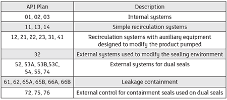
Image 1 summarizes seal flush plans. Flush plans are classified by the first digit to identify if they are single seal (0-4), are dual seal (5), include auxiliary atmospheric quench or leak detection (6) or are gas seals (7). Within each of these seal flush plan categories, there are secondary numbers and sometimes letters that further define the seal flush plan, such as if it includes a filter, includes a heat exchanger or is pressurized or unpressurized.
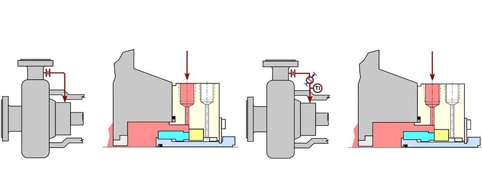
An illustration of two seal flush plans is shown in Image 2. The plan 11 seal flush (left) is a simple product recirculation plan that typically includes an orifice sized to provide the proper flow and pressure at the seal face. The plan 21 seal flush (right) looks much like the plan 11, but it also includes a heat exchanger to condition the temperature of the fluid injected at the seal face.
The seal flush plans illustrated in Image 2 are two common seal flush plans, but they are just two of many flush plans that can be utilized to meet the application requirements. For more information on mechanical seals and flush plans, refer to HI’s guidebook Mechanical Seals for the Pump Industry: Selection, Installation, Maintenance and Troubleshooting – 2nd Edition.