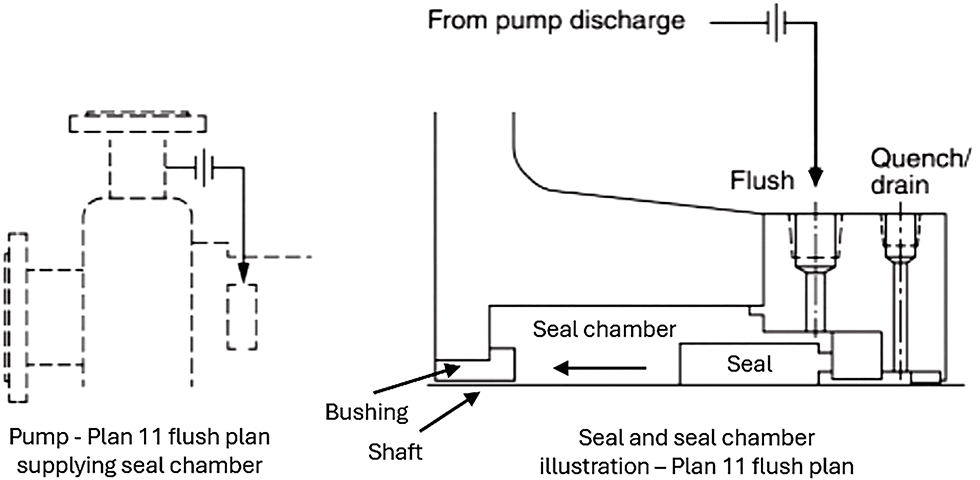
Image 1 shows a pump with a seal flush plan 11, which illustrates the seal chamber being fed from the pump discharge through the flush port. There, it provides cooling and lubrication to the seal and then flows through a close clearance bushing to the back of the pump impeller. In this plan 11 example, the pressure in the seal chamber will be a function of the pump discharge pressure, orifice, bushing to shaft clearance and pressure behind the impeller.
When selecting a seal design, arrangement and flush plan, a primary consideration is if the pressure in the seal chamber is enough to provide a sufficient vapor pressure margin so the fluid can lubricate the seal. Additionally, the pressure is an important factor influencing the closing force between the seal faces, and the seal design may need to be adjusted to accommodate higher pressures. A general rule is to have a minimum vapor pressure margin of 175 kilopascal (kPa) (25 pounds per square inch [psi]) to prevent vaporization from occurring at the seal faces. However, the application engineer will need to consider the full application details, such as:
- If there is a sufficient vapor pressure margin of the process fluid
- Sizing orifices for flows into or out of the seal chamber
- Selection of abrasive separators and other auxiliary equipment
- Selection of a balanced or an unbalanced seal
- The proper face materials for the application
- Seal-generated heat
Consult the HI mechanical seals handbook at pumps.org to see specific K values for different pump types and for details on flush plans for different scenarios.
For more HI Pump FAQs, click here.