

Accelerometers are at the heart of a vibration condition monitoring system. The accelerometer’s ability to sense vibration on a wide range of rotating machines, combined with its economical price and ease of use, have appeal when choosing a condition monitoring sensing technology.
While certainly not the most expensive element in a condition monitoring system, the accelerometer has the most impact on the quality of the data. Accordingly, selection of the accelerometer is the best opportunity to optimize the signal-to-noise ratio of the vibration measurement channel.
Knowing this, condition monitoring practitioners should have a thorough understanding of the technology choices available today in accelerometers. Piezoelectric technology has been available for decades and is widely accepted by the market. Microelectromechanical systems (MEMS) technology, on the other hand, is relatively new but has advanced rapidly and made inroads into the condition monitoring market.
Some Brief History
The use of accelerometers to measure acceleration shock and vibration developed out of the global test and measurement community, mainly for aerospace and weapons development in the aftermath of World War II. Indeed, the first commercially available piezoelectric accelerometer reached the market around 1950. The first documented use of a commercialized accelerometer appeared in the 1920s. Weighing nearly a pound, the device used carbon rings in a tension-compression Wheatstone half-bridge configuration. Interestingly, it was an early precursor to today’s MEMS sensors.
The first silicon-based MEMS accelerometers appeared in the 1960s, as the global test and measurement community aspired to measure higher amplitude accelerations (thousands of Gs) and faster phenomena (shocks occurring within hundreds of microseconds [µs]). These devices were so far ahead of their time that the MEMS acronym was only coined several years later.1
Vibration-based condition monitoring began proliferating in the 1980s, but its adoption increased in the 1990s with the development of the portable vibration data collector and the availability of inexpensive piezoelectric (integrated electronics piezo-electric [IEPE]) type accelerometers.
Fast-forward to today, and a vibration analyst taking vibration data with a portable collector using an accelerometer mounted on a rotating machine has become nearly synonymous with the term condition monitoring. Piezoelectric-based accelerometer technology advancements have plateaued over the last few years, aside from efforts to further extract costs out of the manufacturing process. In contrast, MEMS-based accelerometer technology has advanced in recent years, due mainly to the market’s acceptance of wireless sensors and the industrial internet of things (IIoT).
MEMS accelerometer performance has advanced to where these devices now legitimately compete with piezoelectric accelerometers in condition monitoring applications. Accordingly, condition monitoring practitioners should evaluate the pros and cons of each technology to help determine which solution provides the best value for their production environment.
Key Accelerometer Specifications: Sensitivity & Frequency Response
To fully appreciate and properly evaluate accelerometer performance, two specifications—sensitivity and frequency response—need to be understood.
Sensitivity, sometimes referred to as the sensor’s scale factor, represents the amplitude of voltage signal output for a given input amount of acceleration. Sensitivity is most often expressed in millivolts per unit of acceleration due to gravity (mV/g), with the most common piezoelectric condition monitoring accelerometer found in the market having a (nominal) sensitivity of 100 mV/g. This means that the sensor
will output 100 mV for every g of acceleration to which it is exposed. Although not often explicitly stated on a datasheet, sensitivity is guaranteed by the manufacturer at only one frequency (typically 100 hertz [Hz]).
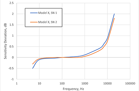
Frequency response (also known as bandwidth) is a way to specify sensitivity over the sensor’s entire frequency range. Accelerometers are dynamic sensors and respond to a range of frequencies. Frequency response can be plotted graphically so that the performance of different accelerometers can be compared.
As shown in Image 1, even two accelerometers of the same model number can have slight differences in their frequency response. Consequently, manufacturers specify a tolerance band in the frequency response so that a batch of sensors that fall within that tolerance range can be classified as the same model number.
For condition monitoring applications, frequency response is the most important factor to consider. Because the frequency range of an accelerometer is not unlimited, it will have a lower frequency limit (typically a few Hz) as well as an upper limit (typically a few kilohertz [kHz]). For example, a commonly used piezoelectric accelerometer for condition monitoring applications is specified from 0.5 Hz to
14 kHz (±3 decibel [dB] tolerance). Of course, to ensure such a sensor is appropriate requires an understanding of the machine to be instrumented. If the application involves a motor-driven centrifugal pump, for example, what is the motor running speed? How many blades does the impeller have?
What are the expected bearing fault frequencies? Because these parameters have characteristic vibration frequencies, knowing them will guide the condition monitoring practitioner in deciding how much frequency range is required of the accelerometer, and, therefore, which accelerometer model to select.
Piezoelectric vs. MEMS: What Is the Difference?
Until recently, frequency response was the biggest difference between the two types of accelerometers, with MEMS devices being limited at high frequency compared to their piezoelectric counterparts. But MEMS technology has improved in the last few years to the point that some MEMS accelerometers are now approaching an upper frequency range of 20 kHz (±3 dB tolerance), matching piezoelectric performance.
Interestingly, early MEMS accelerometers had bandwidths that far exceeded piezoelectric devices. This was because they were originally designed for fast, high-amplitude shock measurements that required a wide bandwidth, but the tradeoff to achieving this was low sensitivity. Some high-shock accelerometers have a sensitivity on the order of 10 µV/g—too low to sense vibrations in rotating machines.
At this point, it is important to understand the concept of damping. Accelerometers are dynamic sensors, and, as such, can be modeled as a dynamic mass-spring-damped mechanical system. Accelerometer manufacturers can control (to a degree) each of these parameters to achieve the performance they are seeking in an accelerometer.
Piezoelectric accelerometers have little damping (and are stiff mechanical systems). As a result, they tend to have wide bandwidths. Early MEMS accelerometers were also designed with little damping (and high stiffness) to achieve a wide bandwidth; as mentioned earlier, this came at the expense of sensitivity. Effectively, a silicon microstructure of strain gauges arranged in a Wheatstone bridge configuration, early MEMS sensors were ohmic in nature.
Today’s MEMS accelerometers, on the other hand, are capacitive in nature, where they are constructed as a silicon microstructure with a variable plate capacitor to achieve greater sensitivity. However, this has introduced more damping into the mass-spring-damped mechanical system, with the side effect of decreased bandwidth. Accordingly, a designer of MEMS sensors must balance the tradeoff of optimizing sensitivity with optimizing bandwidth.
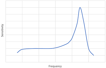
As a result of increased damping, the resonant peak found in the frequency response of any mass-spring-damped system is better controlled than in the frequency response of a piezoelectric sensor. As shown in Image 2, a resonant peak in the frequency response of an accelerometer is problematic in a condition monitoring application, as it can produce false distortion signals that are not representative of the true vibration. It is interesting to note that higher-bandwidth capacitive MEMS accelerometers exhibit a frequency response that resembles that of piezoelectric accelerometers.
Power Consumption & Noise
Electronic noise, which refers to the random low-voltage signals produced by any sensor, is unavoidable simply because of certain real-world factors (friction in a bearing is a similar example). Higher noise levels make it more difficult to resolve fine vibrations that an accelerometer sees.
For some time now, piezoelectric accelerometers have been designed with relatively low noise levels (around 30 µV/√Hz, or microvolt per root hertz). Capacitive-type MEMS accelerometers, on the other hand, have traditionally suffered from higher noise (on the order of 500 µV/√Hz). But high-performance MEMS sensors have improved, enabling them to perform on par with piezoelectric devices.
Power consumption, however, is where MEMS technology has an edge, which is why these types of accelerometers have become particularly useful in battery-powered wireless applications. Whereas MEMS technology typically uses 1 mA or less current, piezoelectric accelerometers use at least 2 mA or more of current (IEPE type) and at least 18 Vdc voltage.
Piezoelectric accelerometers have dominated vibration condition monitoring applications for years, and with good reason. Frequency response, low noise and low cost are the top factors. Nonetheless, MEMS accelerometers have recently made advances in frequency response and noise performance. Along with their inherent low power consumption and low cost, MEMS-based accelerometers now effectively compete with piezoelectric sensors, meaning that condition monitoring users should consider both technologies when instrumenting their plant’s rotating balance-of-plant machines.
References
A more in-depth investigation into the history of accelerometers can be found in the June 2007 issue of Sound and Vibration magazine: The History of the Accelerometer, by Patrick L. Walter.
