

The protection of high-power rotating machinery from unforeseen torque overloads has always been important to extend equipment longevity and maximize operating uptime. In the case of trailer-mounted fracturing (frac) rigs, there is also increasing interest in the use of aero-derived gas turbines as the prime mover for the pump because of their low weight and high output power. The weight of the drive is critical since the frac rig trailers are transported between well sites on public roads, which have government-mandated weight restrictions.
Frac rigs are a costly piece of equipment used in fracking operations to open up a site, and once they are done at one site, they are moved to a new location. Because they operate in remote regions, it is critical that they remain in full operation throughout their time at each site. This makes fail-safe components that allow for quick resets especially important for frac rigs, and driveline couplings are a perfect example of this.
The gas turbine’s coupling design is part of both the rig’s weight consideration and its standard operation since it is needed to effectively transmit the power of the turbine and also protect the driveline.
How Torque Limiters Work
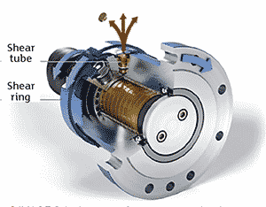
Torque limiters have been used in industrial, marine and mobility applications for years and are available in many configurations and types. Hydraulically pressurized, friction-based types of torque limiting couplings have no backlash. They use shear tubes and a shear ring for the release of the hydraulic pressure after a slip has occurred during a torque overload event. As soon as the pressure is released, the coupling disengages and freely spins without contact between friction surfaces.
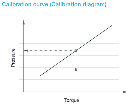
Resetting the coupling is a simple process—the shear tubes are replaced, hydraulic pressure is reapplied based on the desired torque limitation, and the unit is reengaged. Adjustment of the torque limiter setting can be made by referencing the pressure versus torque calibration diagram supplied with the unit.
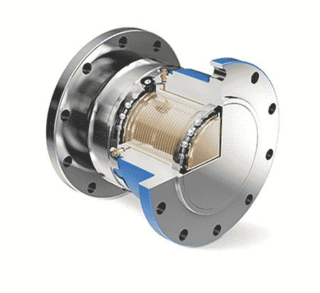
The basic, hydraulically pressurized, friction-based torque limiting coupling is made of an inner and outer sleeve that are assembled and welded at the ends. This assembly forms a twin-walled sleeve that can be oil pressurized up to 1,000 bar/14,500 pounds per square inch (psi) after the machining of the necessary pressurization and shear tube ports has been completed. The design of the shear tube and mating seat provides a sealed system. The size of the torque limiting coupling determines the size and quantity of shear tubes needed. This type of torque limiting technology is the most compact because its transmittable torque grows exponentially with the diameter of the friction surface. Further, the friction surface is treated to prevent wear during the slip phase of the coupling release. Once the coupling has released it rotates on bearings, preventing wear on the friction surfaces.
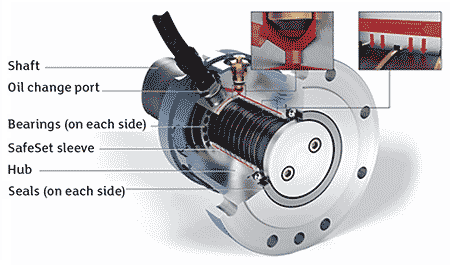
During normal operation, the bearings remain static. The bearings only rotate following the activation of the fail-safe release, which makes bearing life a minor factor when considering the operational dependability of the coupling. Lubrication oil is used for these two reasons:
- As a bearing lubrication during a release condition
- To maintain a constant friction coefficient across the friction surfaces resulting in an accurate release torque relative to the applied pressure
Calibration of the Coupling
As mentioned, hydraulically pressurized, friction-based torque limiting couplings have no backlash and are not subject to material fatigue because the transmitting torque is through a friction surface. The applied hydraulic pressure generates a defined frictional force between the pressure sleeve and the shaft. The applied pressure determines how much torque will be transmitted through the coupling according to the coupling’s calibration curve. The set torque tolerance of the OEM’s torque limiting coupling is +/- 10%. This level of accuracy is possible because none of the torque-limiting parts in these couplings are fatigue-based. Torque limiting coupling designs that use fatigue-based elements, such as pins or springs, to control the release torque can degrade over operation cycles, eventually leading to a false trip of the torque limiter.
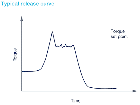
If the operating torque of the machine exceeds the pressure-based torque setting, the driving shaft will rotate relative to the pressure sleeve, which is connected to the driven load. This results in an immediate reduction of applied torque when the friction force changes from static to dynamic. The reduction in applied torque is approximately 30 percent—just within the static to dynamic change of friction.
The shear ring that is fixed to the driving shaft rotates relative to the pressure sleeve and breaks off the top of the shear tubes. Upon this contact, the oil pressure in the coupling drops and the applied frictional force in the coupling is reduced, releasing the torque limiting coupling and fully separating the driving and driven components of the driveline.
Frac Rigs
When selecting a torque limiting coupling for a frac rig, it is recommended that the set point of the coupling is 20% below the maximum torque capacity of the driveline component being protected. By adding a torque limiter, the drive system components can be sized based on the actual operational conditions rather than being based on an estimated worst-case overload torque condition.
When considering a trailer-mounted frac rig drive system, accurate torque protection is more important because a less accurate torque limiter may require upsizing of the weakest component in order to predictively manage the design inaccuracy. A larger component selection, of course, also means a higher trailer weight.
Torque limiting coupling designs can be produced so the coupling is shaft mounted like a hub or flange mounted as if it were a spacer between flexible connection couplings. In addition, it is also possible to provide designs for incorporation directly within a piece of machinery, such as a gearbox. There are also accessories available for use with torque limiting couplings. These accessories include a remote slip detection monitor that can be used as an operator indicator or to force the machine to be stopped.
Maximizing machine capacity and production while protecting valuable rotating equipment is the purpose behind the inclusion of a torque limiting coupling into the driveline of any machine. Use of an accurate, set point repeatable, hydraulically pressurized, friction-based torque limiting coupling will allow for optimal driveline component selection to avoid unnecessary oversizing of components. Right-sizing of components is important for every application but especially those that are mobile, such as trailer mounted frac rigs.
