

Permanent magnet motors (PMMs) for use in water well pumps are routinely referred to as permanent magnet synchronous motors, electronically controlled motors, electronically commutated motors, brushless permanent magnet motors, brushless direct current motors and interior permanent magnet motors.
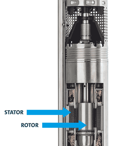
These terms are not always correctly applied to PMMs of all configurations. Here is a simplified look at how electric motors function. In an induction motor, an electrical current is introduced into the stator. As this current rotates through the stator in the form of a magnetic field, it induces a magnetic field in the rotor. The stator and the rotor each have a separate magnetic field.
As the magnetic field of the stator rotates, it pulls the magnets of the rotor, causing the rotor to turn. Since the rotor is locked to the motor shaft, which is coupled to the pump shaft, the pump impellers rotate and water moves.
All motors work by virtue of the rotating magnetic field of the stator, causing the rotor to spin. In the case of both induction motors and PMMs, electricity must be introduced to the stator. The difference between the two is how the magnetic field of the rotor is created. As described above, with induction motors, the magnetic field of the stator induces a magnetic field in the rotor.
However, in the case of PMMs, the magnetic field of the rotor is created during the rotor’s manufacturing process. High-strength permanent magnets are built into the rotor, so there is no need for a magnetic field to be induced. In addition, there can be a considerable reduction in power consumption when using a large PMM, plus many more benefits.
The reduction of energy consumption not only means that PMMs are environmentally responsible, but it also results in lower power costs for the owner. While this may not be a major factor for most small residential systems that do not operate for long periods of time, other applications such as large irrigation and municipal systems with PMMs may gain large savings.
By their nature, all PMMs are operated with variable frequency drives (VFD). As with any VFD-controlled unit, this form of speed control enables the pump to adapt its performance to meet varying flow demands, which is the norm for most of these submersible pump applications.
PMM Benefits
PMMs with small dimensions can run at a higher speed, potentially reducing the number of stages and size of the impellers while achieving target flow rates and heads. This can help 3-inch diameter pumps fit in boreholes that would be difficult for a nominal 4-inch submersible pump to accommodate.
When using small dimension PMMs, increased power density, speed capability and smaller overall size of the PMM results in easier installation and maintenance. Pumps with PMMs are smaller and lighter. While a 1.5-horsepower (hp) induction motor pump weighs approximately 35 pounds, a 1.5-hp PMM pump weighs approximately 16 pounds. PMMs provide a longer winding life by running cooler.
At low speeds, PMMs have a higher starting torque—a benefit in water wells with high mineral concentrations. The pump will have a reduced tendency to seize as minerals build up in tight-tolerance areas within the pump. Further, single-phase PMMs have starting torques that are comparable to that of three-phase induction motors.
Imagine a pump with an allowable speed performance range from 100% down to 28% of full-rated speed. To take advantage of this speed range, the pump is normally operated at a constant pressure setting.
As shown by an example using this curve (Image 3), the pump and motor will maintain a pressure of 60 pounds per square inch (psi), which is 139 feet of head at varying flows from approximately 30 gallons per minute (gpm) down to zero flow. The unit is designed to shut down automatically when demand stops. The VFD-controlled PMM has built-in soft-start, which results in lower shock to the electrical and piping system.
The integrated logic board that comes with the unit provides a wide range of monitoring, self-protection and diagnostics solutions. While the board monitors performance, the resulting self-protection includes automatic reaction to dry run, overload, over temperature and over/under voltage.
Diagnostics include reporting on pressure, temperature, motor speed, power consumption, number of starts and hours of operation.
Alarm functions include dry run, need for service, power supply failure, defective sensor, overload, over temperature, speed reduction, voltage alarm and no contact with the sensor.

In the future, the higher efficiency of larger PMMs may enable these pumps to meet evermore stringent mandates from the U.S. Department of Energy—mandates that are already in place for larger submersible groundwater pumps. Higher efficiency may also help the pump qualify for power use reduction incentives from utility companies. The higher power factor of PMMs may result in an overall lower utility cost for certain applications.
PMMs also lend themselves for use with submersible pumps which use alternative energy sources (solar, wind, batteries, generators and fuel cells) and can achieve flows from 3 to 60 gpm and heads up to 820 feet. These alternative energy pumps have many of the same control, monitoring and diagnostic features mentioned above.
