

Note: For parts 1 and 2 of this column, visit pumpsandsystems.com/author/jim-elsey.
Last month, we discussed pump performance and reliability issues that occur when operating the pump away from the preferred operating region (POR). Running the pump too far to the right side of the curve can lead to cavitation issues and operating too far to the left can create problems due to increased radial thrust and/or other minimum flow thermal considerations.
Gauges
Before we discuss additional pump problems, please realize it is imperative to know specifically where the pump is running on its performance curve, as the operating location (the point of head and flow) will provide the information required to solve the issues.
The lack of gauges or pressure transducers to measure the differential pressure produced across the pump is one of the most common operating sins that I witness. Without some means of measuring the differential pressure, you will have no conception of where the pump is operating on its curve. At the risk of sounding cranky and curmudgeon-like, I will reiterate that the pump will operate where the system curve dictates. Without knowledge of the actual pump operating point or where the system curve intersects the pump curve, you are playing an expensive, irresponsible and losing game of “kill the pump.”
Discharge & Suction Cavitation
Another set of operating issues on the left side of the pump curve are the evil twin brothers, discharge and suction cavitation. These two cavitation phenomena are caused by recirculation of the liquid when the pump is operated on the left side of the best efficiency point (BEP) and the POR. Recirculation is a flow reversal at the inlet and/or at the discharge tips of the impeller vanes. Since specific speed (Ns) and suction specific speed (Nss) are themes that are a little more advanced than a column focused on pump fundamentals should explore, I will only touch on the basic premises.
As I mentioned last month: You may see what appears as cavitation damage on the convex side (the working side or high-pressure side) of the impeller vanes. This is typically due to recirculation cavitation. This damage is not due to insufficient net positive suction head (NPSH) margin but can be attributed to operating the pump in an unstable hydraulic region between BEP and approaching the shutoff point. The actual operating point where the recirculation cavitation will occur is a function of the impeller’s Nss and, to a lesser degree, the volute design.
Nss in its simplest form is a mathematical expression of the design geometry for the suction side of the impeller. Consider the number of vanes, inlet vane angle, curvature and pitch of the vane, the amount of vane overlap and effective impeller eye diameter, to name a few factors.
Depending on the pump’s particular impeller design, the recirculation cavitation issues can occur when operating fairly close to the BEP or they may not occur until the pump is almost at shut off (discharge valve fully closed).
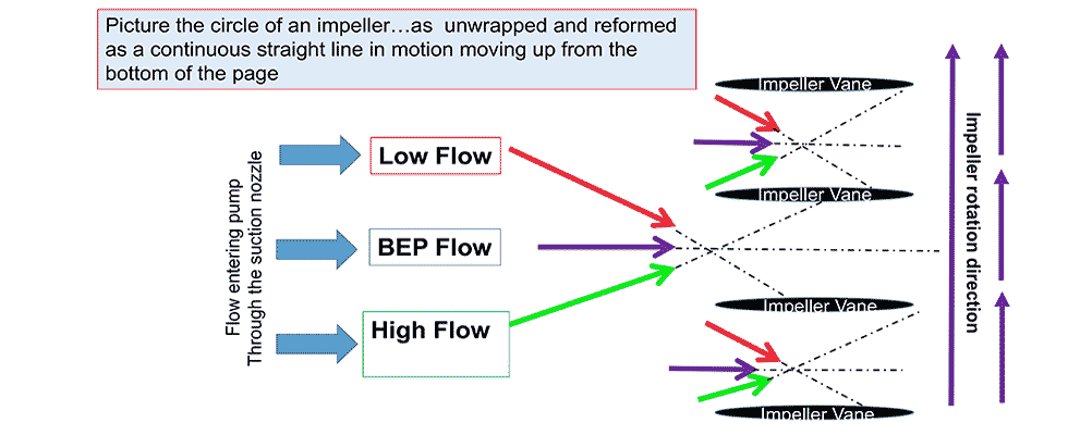
A basic explanation of the recirculation: first the liquid flow enters the area immediately in front of the impeller eye—this can occur at various angles depending on the flow rate (Image 1). At flow rates near BEP, the liquid entry angle will align with the impeller inlet angle, and the pump works as designed with essentially no recirculation. When the flow rate is not at BEP, the incidence angles will be askew. This mismatch in flow angles will create undesired eddies and turbulence in the flow regime. The turbulence results in cavitation.
The other reason for the undesired turbulence is that liquid pressure developed in the casing/volute, due to the higher pressure existing on the left side of the curve, will now create a reversal path and move backward in the impeller creating a recirculation loop. The resultant turbulent flow and the consequential eddies are caused by the mismatch at the impeller discharge coupled with geometric impeller design “compromises.”
The well-intentioned purpose of the design compromises is to gain efficiency and/or NPSH margin. However, these compromises become issues when the design of the impeller eye is too large in the attempt to reduce NPSH required (NPSHr).
Recirculation Pump Tips
- Discharge recirculation is a function of the geometry and proximity from the impeller vane tips to the diffuser/volute (commonly referred to as the gap).
- Discharge recirculation is hard to predict and calculate.
- Discharge recirculation can be reduced but at the expense of pump efficiency.
- The more you design for increased pump efficiency, the closer the discharge recirculation point will be to BEP.
- Suction recirculation is both relatively easy to calculate and predict.
- The higher the impeller Nss, the closer the recirculation point will be to BEP.
- Suction recirculation issues can be reduced but at the expense of increased NPSHr.
- Suction recirculation can occur even on pumps with high NPSH margins.
Submergence
Calculating the NPSH available (NSPHa) to the pump is always an important step in any pump application. Whether the pump suction is flooded or on a suction lift from an open source, an often necessary but overlooked calculation is critical submergence—also called required submergence. Many people incorrectly believe that if they have sufficient NPSH margin that they do not need to consider the submergence criteria.
Excerpt from my April 2016 column:
“Submergence (simple submergence) is simply defined as the distance ‘D’ measured vertically from the surface of the liquid to the centerline of the inlet suction pipe. A much more important descriptive term is required submergence (also known as minimum or critical submergence). Required submergence is the vertical distance, from the fluid surface to the pump inlet, required to prevent the fluid from vortexing and the mitigation of fluid rotation (swirling and or pre-swirl).
“Vortexing will introduce unwanted air and noncondensable gases into the liquid and, in conjunction with causing pump damage, will significantly reduce the pump performance. A centrifugal pump is not a compressor and the performance is significantly affected when pumping dual and/or multiphase fluids (gas and air entrainment in the fluid).”
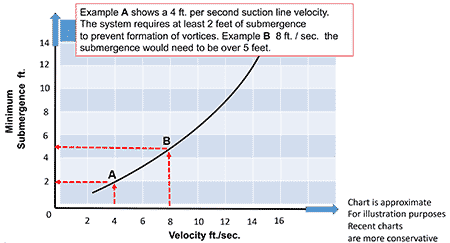
Do not confuse submergence with NPSHa. I always recommend calculation of both factors for the worse expected condition. It is important to remember that you can have adequate NPSHa and still not have proper submergence. The antithesis is also true: You can have adequate submergence and still have insufficient NPSHa. On submergence, the most important factor to be aware of is the liquid velocity at the entrance of the suction pipe. A general set of conservative rules is to keep the suction velocity under 8 feet per second and to have 1 foot of submergence (depth) for every foot of liquid velocity in the suction line.
Boundaries
A common issue with those new to the pump arena is a lack of understanding around pump boundaries. As I state in my training classes “regardless of the manufacturer, you cannot violate the laws of physics.”
Here are some of the more common boundaries and nominal guidelines.
1. Temperature (low and high):
In this case, the temperature refers to the pumped liquid. Most pumps can handle a range of 20 F to 150 F with little issue. Many pumps can handle the range of -40 F to 600 F with some modifications. If you are outside the range of -40 F to 600 F, you will require a specialized or modified pump. Note that the mechanical seal or packing type and support system must also be addressed.
2. Flange ratings maximum allowable temperature and pressure:
A common freshman mistake is to apply pumps outside of their allowable pressure range. All manufacturers will have allowable range charts based on temperature, pressure and material of construction.
Pay particular attention to both the differential and total allowable pressure. I occasionally see a pump rated at 150 pounds per square inch (psi) maximum allowable pressure installed in a system with a 200 psi suction pressure. The pump is only developing 100 psi, so what is the issue?
3. Flange nozzle loading (allowable loads, forces and moments):
The most expensive pipe support anchor you can buy is a pump. Never hang the full pipe loads on the pump nozzles.
Each pump manufacturer will publish established load limits. To exceed the limits will distort the internal alignments in the pump, causing bearings and seals to operate in misalignment and fail.
4. Speed (low and high):
If the pump manufacturer doesn’t have a published curve for the speed range where you want to operate the pump, then do not operate there without checking first.
Speed limits enacted by the manufacturer on the high side are normally due to impeller tip speed limits and inertia issues. Speed limits on the low side are normally established for hydrodynamic stability reasons.
5. Minimum and maximum flow rates:
Running at or near shutoff will require thermal and mechanical calculations. The manufacturer will advise the minimum flow points. Running at the far right end of the curve (maximum rate) is typically fraught with cavitation issues.
6. Liquid personality:
You must consider the properties of the liquid you are pumping and the effects on both the pump and motor.
A quick list would be temperature, specific gravity, pH, vapor pressure, viscosity and the percentage of solids.
7. Brake horsepower (BHP):
All pumps will have a maximum BHP per 100 rotations per minute (rpm) limitation based on both the shaft design and the power frame bearings. Due to side load stresses, these limits are further reduced if the pump is being driven by belts or chains. The shaft limits are also reduced if the pump is being driven by an internal combustion engine. This is due to the shock of the engine’s intermittent torque as opposed to the smooth continuous torque offered by the electric induction motor.
8. Air entrainment:
Most centrifugal pumps will start to air bind at 4% air entrainment and performance will drop off.
9. Suction lift:
If the world was perfect, you could lift liquid from 34 feet, but atmospheric pressure, friction and vapor pressure will knock you back down to a lower, realistic number. Most manufacturers state maximum lift limits around 25 feet based on site elevation at sea level with ambient temperature water.
