

In large industrial applications, often a medium voltage (MV) motor is contributing a large portion of the overall mechanical power and consuming a significant amount of energy. Maintaining these motors is likely mission critical for an application. Likewise, repairing or replacing large motors can pose an extreme impact to process and/or facility operations. Ensuring absolute reliability in a system is cost-prohibitive, but through pragmatic application of appropriate tests, one can still ensure high system reliability.
Testing for MV motors can be extensive and covers a broad spectrum of topics. It is important to distinguish between which tests are standard, mandatory or optional.
Factory acceptance testing (FAT) typically includes safety aspects and basic customer interface. The machine is tested for winding resistance, insulation resistance, polarization index, idle vibration, bearing temperature, etc. These tests are generally prescribed by national and international standards.
What to Expect From a Typical MV Motor FAT
Air gap inspection:
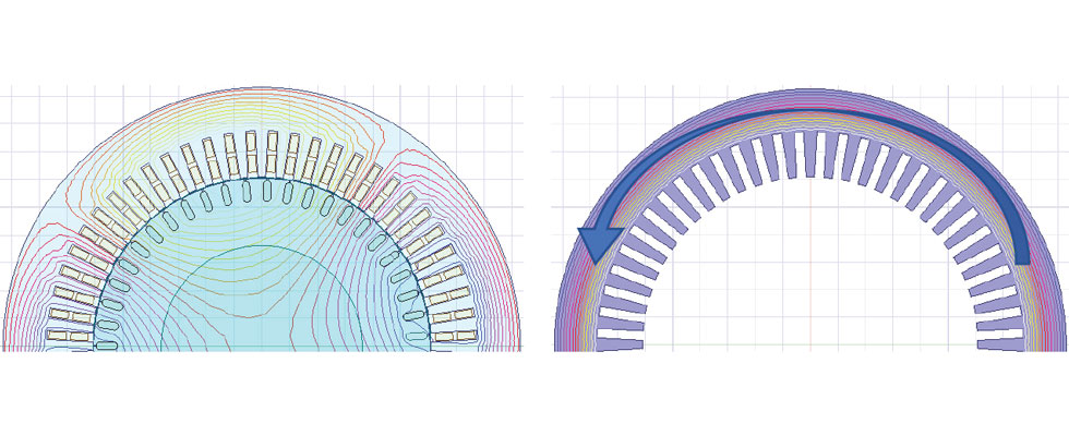
This is executed in two ways. Prior to assembly, the rotor outside diameter is measured in at least two locations as is the stator inside diameter where the difference is twice the radial air gap. After the rotor is inserted and supported in place by the bearings, a feeler gauge is used to verify the air gap dimension in at least four locations. The concentricity of the air gap is critical to smooth operation. Large air gap eccentricity can contribute to magnetic noise, vibration, increased losses and shaft current. In extreme cases, large air gap eccentricity combined with high air gap flux density and/or weak rotor structure can cause a magnetic pull strong enough to prevent motor startup where the rotor is physically contacting the stator.
Bearing insulation resistance:
On motors that use a typical bearing system, flanking the motor at drive end and nondrive end, it is common to insulate at least the nondrive end bearing(s). This arrangement prevents the type of currents from flowing through the motor frame and shaft between the bearings that are generated by magnetic asymmetry. The asymmetry may be slight manufacturing variances, air gap eccentricity, unbalanced applied power, etc. Validating the insulation of the nondrive end bearing resistance may only be accomplished prior to complete assembly with the drive end bearing if the drive end bearing is uninsulated. Additional measures regarding bearing insulation must be taken if exposed to high common mode voltage, as is the case from certain inverters/topologies.
Preliminary alternating current (AC) high potential test:
The purpose of this test is generally related to personnel safety and validating integrity of the motor and accessory insulation. This is performed prior to applying three-phase power. Any failures or disturbances during this test will be limited to the capacity of the high potential test equipment. As it would be sized according to the leakage current of the devices tested, maximum current delivered during a failure is on the order of 2 amps before the voltage is interrupted, as opposed to the short circuit current available from a large transformer or generator.
Winding resistance:
This is measured phase to phase and/or in individual phases. This measurement should closely match the designed value, and the phase resistances should be well balanced. Aside from affecting machine performance, like what was described previously for air eccentricity, unbalanced winding resistance of a large machine can impose an unbalanced load on the connected power system.
Accessory testing:
As there are a variety of sensors and optional accessories included in most motors, they also require some form of validation. Temperature devices should be tested for operation wherever practical. Resistance temperature detectors (RTDs) and space heaters are easy to check element resistance and resistance to ground at ambient temperature, while other devices like solid state thermistors or thermostats may require cycling through the full operating temperature range to verify function. This is impractical in
some cases.
Insulation resistance and polarization index:
This measurement is typically performed in accordance with Institute of Electrical and Electronics Engineers (IEEE) 43.
With an applied direct current (DC) voltage, the current is measured. As the capacitance of the winding is charged from the applied voltage, a measurement is collected at one minute (insulation resistance) and held through 10 minutes. The quotient between these is referred to as the “polarization index.” This test is the most basic health check for a winding, indicating the winding is sufficiently clean and dry and that it is likely safe to apply power. Additional background on this topic can be found in the IEEE standard.
Locked rotor test:
By applying a torque arm to the shaft end and applying a reduced voltage, the locked rotor torque and current can be measured and extrapolated to full rated voltage. This test is critical for aggressive starting loads and for efficiency determination by equivalent circuit method as the locked rotor test is used in approximating the motors equivalent circuit parameters.
Preliminary idle run:
In this phase of testing, the motor direction of rotation can be verified as well as idle performance characteristics (current, power, etc.) to be compared against the specified values.
Magnetic center:
On machines with hydrodynamic bearings, up to around a half-inch of end float is expected. The rotor shaft is marked with the shaft pushed all the way in and again pulled all the way out to the extent of the end float. During the idle run, the rotor will center with the stator due to magnetic forces. That center location can be useful during the alignment procedure required for coupled testing or field commissioning.
Shaft voltage:
Certain asymmetries in the machine construction or supplied power can induce a voltage in the shaft to ground or end to end. It is important to limit these voltages to prevent bearing damage in the motor or driven equipment. Limits can vary slightly depending whether the bearings are insulated or not and which type of bearing is in use.
Bearing cavity pressure:
In cases where hydrodynamic bearings are used, it is important to verify there is no substantial differential pressure from bearing cavity to ambient. Excessive differential pressure is one potential cause of oil leaks through seals. To mitigate excessive differential pressure, equalization ports may be used strategically. Generally, the inboard air seal will see negative pressure caused by the dynamic pressure of the cooling airflow.
A location with a positive pressure ducted back to the bearing could exacerbate this but would normally tend to push oil back into the bearing cavity away from the inboard air seal.
Idle performance:
After verifying proper electrical running conditions for the machine and normal conditions for the bearings, a longer test may be performed to verify bearing temperatures and vibration.
Idle vibration can be used to evaluate a variety of mechanical and electrical criteria, aside from the overall level specific vibration frequencies also being monitored (1x running, 1x electrical, 2x electrical, various bearing frequencies, etc).
Slow roll:
Eddy current probes are sensitive to the magnetic properties of the surface being monitored. Residual magnetism, and inhomogeneity of the steel, can result in a variation between the reading from an eddy current probe as compared to the physical measurement of a dial indicator.
The difference between the mechanical and electrical run out is referred to as slow roll. Slow roll must be corrected or compensated to yield valid shaft vibration measurements.
AC high potential test:
As a final withstand test, the AC high potential test is useful to validate whether a new motor has any internal winding/electrical defect propagating during the previous testing regimen. Certain winding defects may only become apparent after a small amount of applied mechanical, thermal or electrical stress. The motor FAT is generally the first opportunity to apply three-phase power to a machine, where turn-to-turn stress is applied throughout the entire winding as compared to a
surge comparison test, which will apply the majority of stress to the first coil in a winding.
The extent that a manufacturer uses in-process testing and which aspects of FAT are included may determine an expectation of quality. These tests, as well as the material testing, should cater to the specific product and application. Unusual service conditions may drive some testing requirements related to extremely low ambient temperatures, abnormally wet or salt-laden environments, and corrosive environments (e.g., chlorine, sulfuric acid, etc). Machines with aggressive starting profiles, or weak power supplies, particularly low vibration requirements, efficiency requirements and noise emission requirements may each benefit from specific additional testing or type testing.
A type test may include direct or simulated load heat run. The heat run facilitates further ability to measure power factor and efficiency, hot vibration, etc. The type test may include a locked rotor curve and a speed-torque trace. Typically included are noise level measurements, and in certain cases, stray loss measurement.
A direct coupled heat run may be costly but should be considered when operating temperature, vibration or power consumption are critical data points to ensure system reliability. Different methods of achieving the required load or simulating the required load may be used—in accordance with governing standards—but keep in mind the limitations of each.
Typical methods for direct applied load may be using a generator or a dynamometer. Alternatively, means to apply a simulated load may be used, including mixed frequency test, forward stall or superposition.
Additional aspects would need to be tested to measure stray loss. Indirect measurement of stray loss may be accomplished by a “reverse rotation” test along with a test on the stator alone, or by EH-Star method or direct measurement using a torque cell.
Due to the nature of these loading techniques, a situation may exist where measurement of coupled vibration is not possible using a mixed frequency equivalent load or where a measurement of hot coupled or uncoupled vibration may require additional testing points to achieve the target temperature.
The extent of testing typically included in FAT, as compared to the additional rigors involved in a type test, can result in the associated cost increasing accordingly. Certain aspects of that cost could be avoided if the entire gamut of testing is not required for the given application.
There are many more testing methods for various parameters, but the methods listed here are considered the most practical collection of tests to achieve a high confidence in product quality.
