
Alignment is when all pump, driver and coupling centerlines fall within the same centerline. Misalignment occurs when the centerlines are offset or angular from each other. Balancing is the act of redistributing the mass of a part so that the mass is evenly distributed around the part’s rotating axis. Imbalance occurs when the mass center axis is not aligned with the geometric axis. The mass center is the midpoint that the assembly tries to rotate around naturally. The pump impeller would spin around this axis if it were thrown spinning through the air. The farther these two centerlines are apart, the more imbalance an assembly will see. The end result of balancing is to align the mass center with the geometric axis. Pump and drive shafts must be aligned in order for the assembly to be in alignment. A user must start with a good pump, driver and coupling in order to dynamically balance an assembly. Any components that are not dynamically balanced can result in accelerated seal and bearing failure. Once bearing failure occurs, the pump assembly will need to be rebuilt. Misaligned external forces mimic those of imbalance because misalignment causes excess vibration. Misalignment can be caused by improper assembly of components, shifting of components after assembly and changes in temperature. Often, misalignment is the cause of imbalance that cannot be corrected by balancing.
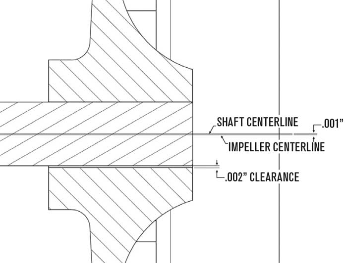 Image 1. Typical pump assembly. (Images courtesy of Hines Industries)
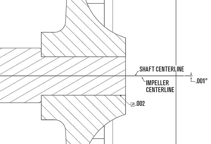 Image 2. Impeller bore to shaft clearance.
Balancing
The force created by imbalance increases exponentially with speed. Tolerances for imbalance are set with operational speeds in mind. Force = Imbalance x Speed2 Equation 1 Force imbalance is the imbalance as measured on a single plane and is perpendicular to the axis of rotation. Force imbalance is a condition that exists when the center of mass is not on the axis of rotation. Static imbalance by itself is typically measured and corrected on narrow disc-shaped parts, such as a Frisbee. A single plane balance is required for impellers with the D/B ratio greater than 6. B is the distance between the impeller shrouds and 1 inch from the impeller outside diameter. D is the diameter of the impeller.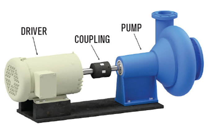 Image 3. Runout in the shaft pump rebuilding section.
Pump Rebuilding
When rebuilding pumps, several things need to be looked at to define the root cause of imbalance:- Runout in the shaft: This is one of the causes of imbalance in the assembly. Shaft runout will hold the impeller off center therefore creating an imbalance. An example would be a 200-ounce impeller with a shaft having 0.002-inch runout will actually offset the pump impeller centerline by 0.001 inch, which would result in a 0.2 ounce/inch imbalance. To eliminate runout in the shaft, the shaft must be straightened or replaced.
- Impeller bore to shaft clearance: This can also cause a pump unbalance as described in this example. An example is a 200-ounce impeller with a bore to shaft clearance of 0.002 inch will actually offset the pump impeller centerline by 0.001 inch, which would result in a 0.2 oz/in imbalance. An impeller bore to shaft clearance must be minimized to ensure a balanced assembly. A perfectly balanced shaft with an imperfect clearance will cause pump imbalance. To minimize the impeller bore to shaft clearance in a used pump, both the shaft and impeller should be inspected to verify if the shaft is undersized and/or if the impeller hole is oversized. The solution is to replace the shaft and/or the impeller to minimize the shaft to bore clearance.
- Unbalanced impeller component: This can also cause imbalance within the assembly. A perfectly balanced shaft with a minimal clearance with an imbalance impeller still causes an imbalanced pump assembly. There are many ways to correct imbalance, such as adding or removing weight to the assembly. If this is not feasible, the impeller needs to be replaced.
Benefits
There are many benefits of balancing and aligning pump assemblies:- decreases vibration—minimizes wear and increases longevity of pump assembly
- reduces heat and friction—increases the life of bearing and seals
- diminishes noise—reduces the noise to an acceptable decibel (dBA) level
- increases system life cycle—less overall maintenance, downtime and costs
- increases system life efficiency—less energy to run and operate
- saves time and money—see all of the above
