

Throughout the nuclear power industry, equipment suppliers are exiting the nuclear marketplace. Utilities and component manufacturers are turning to innovative methods for replacement of obsolete parts that cannot be procured as safety-related or certified to American Society of Mechanical Engineers (ASME) Boiler and Pressure Vessel Code (BPVC) Section III.
Investment in obsolescence management is widespread, with a focus on development of more extensive reverse engineering and commercial grade dedication procedures to ensure pathways for component replacement. OEMs have the added capability of assessing component design and service history to make technical design changes to overcome procurement barriers, as well as improve aspects of in-service operation.
This case study examines a system reconfiguration to eliminate a problematic solenoid valve from a bearing lubrication system for an essential service water (ESW) pump. Elimination of the solenoid valve solved procurement issues (the valve could not be purchased from a 10CFR50 Appendix B supplier), as well as valve clogging issues that had resulted in reduced service intervals for the end user.
Application
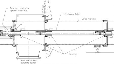
The ESW pumps are single-stage, vertical turbine pumps that provide a continuous supply of seawater—28,000 gallons per minute (gpm)—to the tube side of the component cooling water heat exchanger in a pressurized water reactor (PWR) system. The ESW pumps operate during all plant conditions, including design-basis events, to cool plant equipment necessary for safe shutdown.
Each ESW pump has enclosed line shaft bearings and employs an integral bearing lubrication system for cooling and lubrication of the six bearings along the length of the pump. The system supplies pressurized lubrication flow to the bearings prior to pump startup and continues supply throughout operation. Lubrication flow is injected at the stuffing box beneath the gland packing and doubles as the source of gland leakage flow.
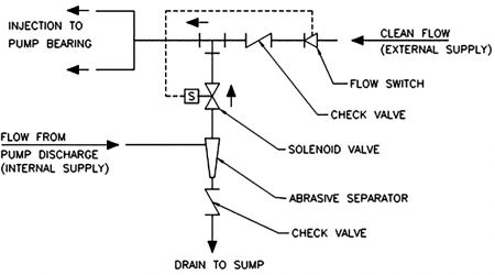
The bearing lubrication system has two modes of operation: external supply and internal supply. During external supply, which is the normal mode of operation, clean water is supplied from an outside source. Backflow through the internal supply line was originally blocked by a flow-activated solenoid valve. Internal supply is a backup operating mode and is only activated upon failure of the external water source. During internal supply, lubrication flow is routed from pump discharge and allowed to enter the system. The original system used an electric flow switch to open the solenoid valve for this operating mode. Bypass flow is filtered through a cyclone abrasive separator prior to injection to the bearings. Backflow through the external supply line is checked. A schematic of the original system is shown in Image 2.
Problems
During review of an order for replacement bearing lubrication systems, it was determined that the solenoid valve and corresponding electronic flow switch could not be procured as safety-related or certified to ASME BPVC Section III; there were no viable 10CFR50 Appendix B suppliers for the original components. Purchasing as commercial grade and upgrading via commercial grade dedication, a process often implemented in these scenarios, proved impractical due to a lack of sufficient design information from the original component manufacturers.
In addition to procurement issues, problems with clogging of the solenoid valves were identified during technical discussions with the end user. The ESW pumps operate in a particularly harsh seawater environment; the pump intake bay contains a large amount of suspended particulate and sediment. Even after filtering through the abrasive separator, particulate from the process fluid accumulated in the solenoid valve over time. The clogged valves resulted in decreased service intervals and unplanned system maintenance for the end user. Complete shutdown of the ESW pumps is required for valve cleaning.
System Redesign/Reconfiguration
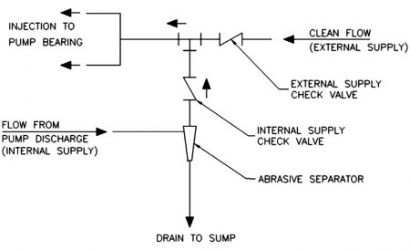
After thorough review of the bearing lubrication system, a reconfiguration was designed and implemented that eliminated the solenoid valve and flow switch altogether while maintaining the functionality of the original system. In the revised configuration, the drain line check valve is relocated to the filtered water discharge of the abrasive separator, replacing the solenoid. A schematic of the reconfigured system is shown in Image 2.
The original system used flow-controlled electric actuation of the solenoid valve to switch from external to internal lubrication in the event of external supply failure. When clean flow dropped below a minimum lubrication flow of 3 gpm, the solenoid valve was actuated by the flow switch to permit self-lubrication flow to the bearings; internal supply would continue until restoration of external flow, at which point the solenoid valve would deactivate, halting the injection of process fluid to the bearings.
Conversely, the reconfigured system is a pressure controlled, passive system using check valves only. The lubrication mode is self-selecting based on the pressure in the internal and external supply lines. The source with the highest pressure at any given time dominates and lubricates the bearings without the need for external power supply or signaling between components. During normal operation, external supply pressure is maintained above pump discharge pressure for constant clean water lubrication. Upon loss of external supply pressure, the system automatically shifts to self-lubrication.
The separator drain check valve was deemed noncritical to system operation and was repurposed as the internal supply valve. The drain valve was originally intended to prevent backflow into the system, but backflow contamination would require an unlikely rise in sea level above the sole plate of the pump.
If this occurred while the pump was running, the portion of the flow through the bypass line exiting the separator drain would prevent ingress of raw seawater. If both the pump and external water supply were off, the total volume of ingress past the cyclone separator would be insignificant, and the raw seawater would be flushed from the enclosing tubes upon startup of the pump with a negligible impact on bearing life.
The reconfiguration resulted in reduced drain line resistance due to removal of the separator drain check valve, as well as increased internal supply line resistance due to a lower flow coefficient (higher flow resistance) of the internal supply valve; the flow coefficient of the internal supply check valve is 1.9 (Cv = 1.9) while the flow coefficient of the original solenoid valve was 4.0 (Cv = 4.0).
To validate that internal lubrication flow would remain sufficient in the revised configuration, an iterative flow analysis was performed to determine flow rate to the bearings. Both the new and original system configurations were analyzed, and the anticipated self-lubrication flow rate was compared based on the rated head of the pump (133 feet, 59 psi). The results indicated that the internal supply flow to the bearings in the reconfigured system remains above the minimum 3 gpm flow rate dictated by the original design.
Results
Elimination of the solenoid valve and flow switch precluded procurement issues, allowing fulfillment of the order while minimizing the effects of obsolescence on both the supplier and end user. The check valves used in the revised system are easily sourced; the valve bodies are manufactured in-house, with valve internals purchased and dedicated via material analysis and functional testing. The reconfiguration eliminated clogging issues associated with the solenoid valve and, thereby, will reduce system maintenance.
The updates reduce system complexity while maintaining the dual supply requirement of the original system. The reconfigured system is passively self-regulating and uses fewer components, reducing potential failure points. The result is a more robust design with the added benefit of direct reduction in overall system cost.
