

Pump gas seals incorporating noncontacting gas sealing technology have been available in the industry for over 25 years and are growing in popularity. With tightening restrictions on emissions and a greater focus on energy efficiency in plant and refinery operations, pump gas seals are becoming a preferred technology to meet current and future environmental objectives. This technology enables zero process emissions to the atmosphere and can be achieved with one of the lowest carbon footprints of the available mechanical sealing technologies.
Noncontacting Dual Gas Seal Support System: API Plan 74
An American Petroleum Institute (API) Plan 74 supporting a dual pressurized non-contacting pump gas seal provides a controlled gas barrier to prevent the escape of pumped fluid to the atmosphere resulting in zero emissions of the fluid. Plan 74 delivers clean pressure regulated barrier gas to the dual pressurized pump gas seal, allowing the noncontacting features of the mechanical seal to function.
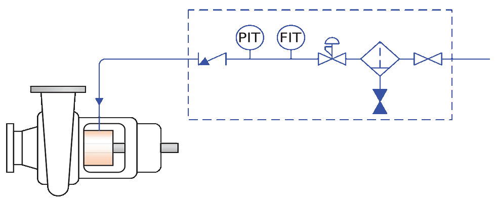
Instrumentation in the Plan 74 provides the user the ability to monitor the gas pressure and flow being delivered to the mechanical seal. Flow measurement can provide an indication of the mechanical seal’s health. Deviations from normal barrier gas flow rates can be an early indication of the deterioration of seal performance. A Plan 74 system panel typically contains a group of instruments mounted in series whose purpose is to:
- clean the barrier gas
- regulate and monitor the barrier gas pressure
- monitor the barrier gas consumption flow rate
By contrast, the operation of an API plan 74 supporting a dual pressurized gas seal is simpler than a liquid lubricated seal system.
Contacting Dual Wet Seal Support Systems: API Plans 53, 54
Dual pressurized mechanical seals can meet strict emission requirements enabling zero emission of pumped fluid. The liquid barrier support system of such a seal can become a complex apparatus and often requires engineering to ensure it will meet the needs of a given application. The system must perform the following functions:
- provide a reliable source of liquid to separate the pumped media from the atmosphere
- dissipate the heat load absorbed by the barrier fluid
- provide an early indication of when the mechanical seal performance begins to deteriorate
To meet these needs, a liquid barrier system must consist of a lubricating fluid in a circulating loop, incorporating a reservoir in the form of a vessel or accumulator, a heat exchanger (typically water-cooled) and a means of circulating the barrier fluid.
Periodic replenishment of barrier fluid is required to replace the liquid consumed during normal mechanical seal operation. The heat load on these liquid barrier systems increases as process pressure and temperatures increase, so these systems must be correctly sized to maximize the system’s operational reliability. These liquid barrier systems have specific commissioning, operational and maintenance plans that are essential to achieving reliability.
Sensitivity to Water Quality
Many systems installed on higher duty services utilize a water-cooled heat exchanger to handle the significantly higher heat loads than that of comparative oil-cooled bearings and other typical rotating equipment in a plant. The quality of the cooling water supplied to the heat exchanging equipment can have a major impact on the performance of the sealing system. With higher heat load demands, the quality of the cooling water becomes more critical. Even changes in the ambient temperature of the cooling water supply can have drastic effects on the performance of the sealing system. Impurities and contamination in the water supply can lead to fouling of the heat exchanger, reducing efficiencies and shortening the life span of the equipment.
High Temperature Sealing Advancements for Noncontacting Seals
Recent technology developments are enabling pump gas seals to reliably operate in more challenging environments. Incorporating noncontacting gas seal technology alongside established high temperature metal bellows seal technology has allowed pump gas seals to be applied in high temperature applications up to 800 F (425 C) and as low as -100 F (-75 C). These advancements are increasing the scope for pump gas seals to seal a wider range of applications.
Applying a pump gas seal in a hot application can eliminate the need for a complex liquid lubrication system
and their dependence on a heat exchanger to dissipate the heat absorbed into a barrier fluid.
Liquid Lubricated Seal vs. Pump Gas Seal
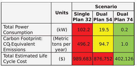
The Fluid Sealing Association provides a life cycle cost (LCC) estimator tool that helps compare life-cycle costs of various sealing solutions to assist in decision-making when specifying capital projects or upgrading existing rotating equipment technology.
The LCC tool takes in input criteria for up to three scenarios and considers operating costs, one-time costs, present value calculations, power consumption calculations and carbon footprint to compare total estimated LCC for each scenario. Comparing the LCC of the following three scenarios for a 2.75 inch (70 mm) shaft seal operating in a high temperature, 680 F (360 C) service at 100 pounds per square inch gauge (psig)
(7 barg):
- A single liquid lubricated seal operating with an external flush API Plan 32
- A dual pressurized liquid lubricated seal operating with API Plan 54
- A dual pressurized dry gas seal operating with API Plan 74
Looking at the output categories from the LCC tool, the total power consumption and carbon footprint of the dual gas seal scenario is exponentially lower than that
of the liquid seal contenders. This is primarily due to the noncontacting seal face technology inherent in pump gas seals as well as the eliminated need of a Plan 32 flush.
Comparison of the scenarios from a total estimated LCC perspective (25 years) shows a dual pressurized gas seal can offer a substantial savings compared to that of a conventional dual pressurized liquid lubricated seal all while meeting the environmental requirements and ensuring zero emissions operation.
What Are Potential Drawbacks of Switching to a Pump Gas Seal?
1 - Barrier gas ingress into the process stream
Barrier gas is consumed during normal operation of noncontacting dry gas seals and migrates into both the process stream and to the atmosphere. The end user must be aware of this. Having a closed loop pumping system would be an uncommon scenario, but it would be one where the barrier gas consumed into the process fluid could accumulate and cause issues with pumped fluid circulation.
Potential impacts of barrier gas ingress into the process fluid are chemical reactions, catalyst contamination or a dilution of the pumped fluid. It is important to recognize these facts, especially when considering pump gas seals on vessels, closed loop systems or sensitive chemical applications. The amount of ingress of barrier gas will be dependent on the operating conditions of the process and Plan 74.
It is important to maintain a set differential pressure for the barrier gas above the process pressure. Exceeding the barrier gas differential pressure range can increase barrier gas consumption and could increase the ingress of barrier gas into the process to undesirable levels.
2 - Supply of barrier gas
API Plan 74 requires a source of dry barrier gas (typically nitrogen) to the Plan 74 support panel. Typically, this comes from a plant-wide nitrogen piping system. The substitution with compressed gas bottle racks is not recommended, as the consumption and replenishment rate may result in running out of compressed gas, essential for seal operation.
3 - The necessity to amplify the barrier gas pressure above that of the process fluid pressure, typically 30 to 50 psig
When the available gas supply pressure is low, the gas pressure may need to be amplified by means of additional pressure boosting equipment if the capability for this does not already locally exist.
4 - Small seal chambers
As with any mechanical seal, there are limitations when adapting seal designs into older pumps not specifically designed for mechanical seals that have smaller seal chamber/stuffing box envelopes. Some standard pump gas seal designs may require a larger than available cross-sectional space to fit the necessary hardware and components of the seal design.
Additional Benefits
The LCC of a noncontacting high temperature seal with API Plan 74 is less than that of a high temperature wet seal and seal support system. Applying a pump gas seal in high temperature services enables plant operators to achieve even greater cost reductions and improving efficiencies within the plant.
Additional benefits include:
- elimination of expensive API Plan 32 flushes in many applications
- elimination of barrier fluid disposal costs, cooling water requirements, fouled heat exchangers and costs associated with emission monitoring programs
- lower power (energy) requirements
- reduction of carbon footprint
- zero-emissions to atmosphere
There are many examples of pump gas seals replacing dual pressurized liquid seals in installations where mean time between maintenance and repair (MBTR) has been extended, leading to direct cost savings and extended time between unit and plant wide turnarounds.
We invite your suggestions for article topics as well as questions on sealing issues so we can better respond to the needs of the industry. Please direct your suggestions and questions to sealingsensequestions@fluidsealing.com.
