
Houston, Texas, gets hot during the summer, with temperatures exceeding 95 F (36 C) in August and 90 F (33 C) for an average of 102 days a year. While air conditioning helps to make life tolerable during Houston's hot, humid days, there is no such relief for pipelines that are pumping oil and gas products. Keeping pipeline components in optimal condition is a constant challenge for oil and gas companies that must contend with the effects of rising temperatures on liquid pump seals. Recently, one company solved a similar problem with the seals on its ethane pumping system by incorporating a dry gas seal in a liquid-pump application. The end user, located in Houston, operates natural gas liquid (NGL) fractionation facilities, where it processes mixed NGL streams into purity NGL products including ethane, propane, normal butane, isobutene and natural gasoline. A crucial part of its operation is the ethane injection pumps that pump ethane from 410 pounds per square inch (psi), or 28 bar, to about 1,100 psi (76 bar). While the ethane temperature at suction should be approximately 60 F (16 C) on a typical warm, Houston summer day, this temperature can increase dramatically. The increased temperatures result in seal failure, which can cause ethane to vaporize—resulting in product loss.
Why Liquid Pump Seals Fail
When operating rotating equipment, some end users do not pay enough attention to transient conditions. Startup, slow-roll and standby pump conditions must be evaluated to ensure proper sealing fluid is being supplied to the seals at all times.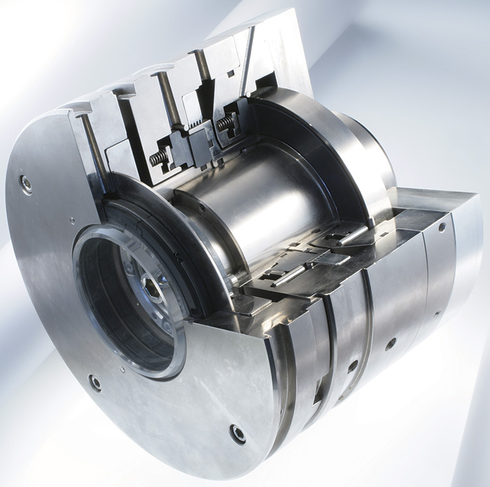 Image 1. Typical design of a dry gas seal (Image and graphic courtesy of EagleBurgmann)
- Startup: The pump is charged, but at or near suction pressure. Liquid ethane at the seal faces is slowly leaking and vaporizing. When the pump starts, how long does it take to build the right pressure in the stuffing box and get the pressure above vapor pressure? Additionally, the heat generation between the faces, although not significant, could be enough to increase vapor pressure and vaporize the fluid across the faces. Damage to sealing faces could be a telling sign that this is occurring.
- Slow-roll: The same situation as startup but compounded. Without the right speed, the discharge pressure is not generated. The pressure in the stuffing box is not rising quickly enough to ensure the ethane will reach a high enough pressure to overcome the vapor pressure. Also, the heat generation between the contacting faces is increasing, and damage is probably taking place.
- Standby: All conditions mentioned above are the same, but the seals are sitting idle for many months without a flush to the seals. During the standby time, evidence has shown that debris has collected at or around the seal faces, which, in turn, adds more complication to the sealing environment.
- Inefficient operation: Operating the pump too far outside of the best efficiency range and with the wrong operating parameters results in increased demand for drive power and reduced discharge pressure. Both of these negatively impact the vapor margin in the seal area, which can result in dry running.
Meeting the Challenge
Low vapor margin applications, such as ethane, have one thing in common: The liquid would rather be a gas. For this reason, many end users incorporate liquid-lubricated gas seals. The manufacturer that supplied the seals for the facility in Houston, for example, offers pump seals that run on a gas film between the faces—either a dual pressurized seal using an inert gas or a dual unpressurized seal with the outboard seal operating on a gas. A dual unpressurized seal works great in these applications, but transients and other unknowns can cause problems. Incorporating a clean gas at the seal faces helps prevent failure, but certain problems can persist. When the manufacturer was evaluating these challenges, the Houston facility's initial solution was to use liquid-lubricated seals and take discharge pressure directly into the stuffing box. But the liquid-lubricated seals continually failed, especially on warm summer days as the outside temperature rose. The reason had to do with the inherent nature of ethane For ethane to remain in its liquid state, it must be kept at a certain temperature and a certain pressure (approximately 300 to 400 psi [21 to 28 bar]) at 60 F [16 C]). If the pump is operating properly and the pressure and temperature are at their ideal points, then the ethane continues to flow as a liquid. But as the outside temperature rises on a warm day, the pressure and the temperature of the pump also increase. This causes the ethane to vaporize at the seal.Transient Conditions
Liquid-lubricated seals are designed to handle liquids only; they will fail if they are suddenly confronted with handling a gas, such as when ethane vaporizes from a liquid. In reality, a liquid-lubricated seal can be successful in an ethane application, but only under conditions that do not change. Because the seal environment kept changing in the Houston application, the liquid-lubricated seals could not work properly. Liquid-lubricated seals work best in environments where the temperature and pressure are at a consistent level. For this end-user's operations, it was the transient conditions that caused the problems. For this application, ethane was sealed. For ethane to become a gas, it needs a pressure drop or a vapor pressure increase above the sealing pressure. Heating the fluid is a quick way to achieve this, but using an external heater adds complexity and maintenance. Using a close-clearance, multi-tooth labyrinth on the front end of the seal causes the turbulent flow during operation to create fluid friction that will build heat. The rotation of the seal faces also adds heat. The closer the gap is between the faces, the smaller the leakage and the higher the heat generation. But the transient conditions caused problems. Relying on rotation to build heat ignores the effects of startup, slow-roll and the standby pump.Dry Gas Seals
The solution—a dry gas seal—was simple, though a bit unconventional. This technology is usually not used in liquid-pump applications, but it seemed to be a good solution because the ethane liquid wants to be a gas. Dry gas seals delivered enhanced reliability in operating modes where the seal faces are in constant contact—turning, ratcheting, coast-down and other operating modes that create critical conditions for standard gas seals. Experience has shown that unexpected operating situations, such as the transient conditions the end user was experiencing, can compromise a gas seal. Because seal faces are designed primarily for non-contact operation, they are subject to wear when there is contact for sustained periods. This can cause seal failure resulting in downtime and production loss. These seals featured bonding that consisted of a micro-crystalline layer that has attributes of natural diamond. For example, it will not flake or chip off, the coating is extremely hard and wear-resistant, and it offers excellent heat conductivity and high chemical resistance. These dry gas seals can be ideal solutions for extreme operating conditions. They can extend the recommended repair intervals for mechanical seals to at least five years. This technology also provided simplification of the sealing system. In this application, the liquid ethane is very clean. It is typical to filter the ethane prior to injecting it back in the seal area; otherwise, there is a risk of damage to the dry gas seal faces. A filter flush can increase the stuffing box pressure, which increases the vapor margin and makes it more difficult to vaporize the liquid. Instead of using a flush, if some particles were in the liquid, the special bonding would either crush them, or if they are small enough, the special dry gas seal groove pattern would pass them along. No filters were needed, which reduced maintenance costs and downtime.Successful Application
The dry gas seals were installed in July 2011. After several months, plant operators reported that they had seen at least an 83 percent reduction of the ethane to their flare system. Today, it is above 90 percent. Eight months into operation, the end user took the pumps out of service for an impeller re-rate. The seals were removed and transported to the manufacturer's facilities for a teardown and inspection. When the seals were opened, the faces looked new. The components were cleaned, and the seals were tested. The leakage rates were slightly lower than what was originally recorded. The end user decided to install the seals back into their pumps and run them without repair. Currently, the seals are still running with no issues. This technology is being used in more types of services with different light hydrocarbons and in a carbon dioxide application.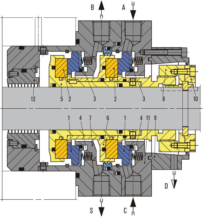
Example of Tandem seal with intermediate labyrinth
The details of this seal include:
- Seal face, stationary
- Seat, rotating
- Thrust ring
- Spring
- Shaft sleeve and seat retainer
- Intermediate sleeve
- Housing (adapted in size to the installation space)
- "Adjustable" nut for axial misalignment
- Split ring
- Tension ring
- Cover
- Process side labyrinth
GBI is gas buffer inlet, GBO is gas buffer outlet and D is drain. The yellow parts are rotating, blue are stationary, and gray represents pump shaft and housing.
