
Gasket failures can be problematic, causing unwanted downtime, revenue loss and safety concerns. Failure analysis shows that up to 85 percent of all gasket failures are due to faulty user installation, though it is important to note that with proper training and installation procedures, most of these failures are preventable. ASME PCC-1 is a post-construction guideline for pressure boundary bolted flange joint assemblies, and the bulk of gasket manufacturers derive their installation procedures from this guideline. For the end user who does not have an installation procedure, it is a great resource to have; however, the book is more than 99 pages and is not suitable to carry around in the field. To help with this, the Fluid Sealing Association, (FSA), in conjunction with the European Sealing Association, (ESA), have created a Gasket Installation Procedures pocket book (available in nine languages on the FSA and ESA websites, fluidsealing.com, europeansealing.com) to help installers focus on the key points of proper gasket installation. Following is a summary of the six principal areas of focus in sequential order.
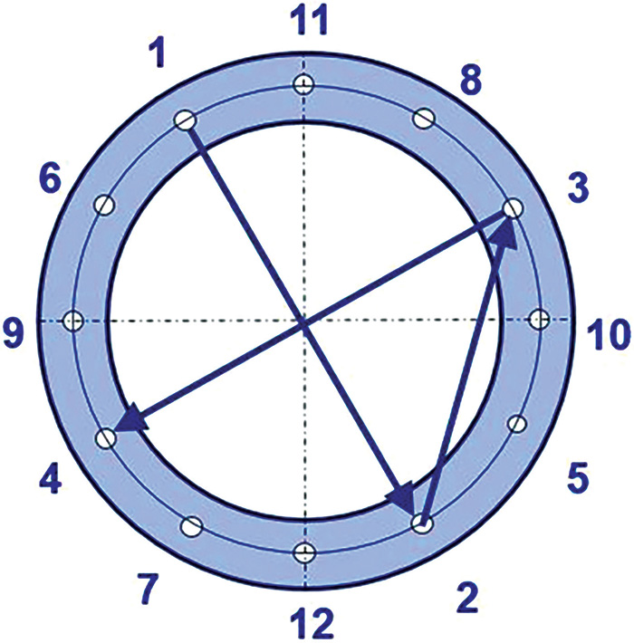 Figure 1: Legacy method or cross-bolt tightening pattern (Graphics courtesy of FSA)
- calibrated torque wrench or other tightening device
- wire brush
- hard hat
- safety goggles and/or face shield
- lubricant
- other plant specified equipment
Step 1: Clean and Examine
Once the gasket has been removed from the flange, remove any foreign material or gasket debris from the sealing surface. Using a wire brush, physically remove any material embedded in the sealing face or flange serrations. Be careful not to use a grinder, hammer and chisel, or abrasive material that could further damage the flange sealing surface. Inspect the sealing face for dents, dings, mars or pitting that could cause sealing issues. If there is any noticeable flange face damage, you can refer to ASME PCC-1 Appendix D—guidelines for allowable gasket contact surface flatness and defect depth, to determine if repairs to the flange are required. Inspect fasteners such as bolts, washers and nuts for defects, cracks and burrs. If fastener components are determined to be defective then discard and replace.Examination Tip:
When inspecting bolts and nuts, make sure that nuts run freely over the threads prior to installation to ensure there is no damage to the threads.Step 2. Align Flanges
To create an effective seal, the installer must ensure that the flanges are parallel as they are brought together. This gives the best chance of applying a uniform maximum gasket load, creating the best seal. ASME PCC-1-2013 Appendix E—Flange Joint Guidelines, gives the recommended allowable limits for:- flange parallelism
- centerline high/low (the alignment of inner diameter (ID) of the flange bore or outer diameter (OD) of the flange meet)
- rotational-two hole (rotational alignment of bolt holes to allow the insertion of fasteners without binding)
- excessive spacing, which is defined as when the distance between the two flanges is more than twice of the gasket thickness selected
Alignment Tip:
Avoid using a pry bar or screwdriver to align flanges. Proper tools are available to help with both linear and rotational alignment that are safer and easier to use.Step 3. Install Gasket
Before installing, inspect the gasket to ensure that it is free of defects and that it was cut cleanly with no rips or tears. Carefully insert the gasket between the flanges, making sure it is centered between the flanges. In the case of difficult or horizontal installations, never apply release agents or joint compounds on the sealing surface of the gasket. Doing this causes two main problems:- The joint is now lubricated making it easier for the gasket to extrude from the flange as a result of internal pressure and hydrostatic end forces that are acting upon the joint.
- The material can cause a chemical attack on the gasket, compromising the gasket properties and its service life expectancy.
Installation Tip:
For full face gaskets, inserting two to three bolts through both flanges and gasket will help locate the gasket and keep it from moving while bringing the flanges together, reducing the risk of pinching or damaging the gasket.Step 4. Lubricate Load Bearing Surfaces
Lubrication or anti-seize is a critical step in any gasket installation. It helps with the assembly and in the case of anti-seize, also helps with the disassembly. It is important to consider factors such as temperature, particle type and size when selecting the proper lubrication or anti-seize paste. Without using a high-quality lubricant/anti-seize with a consistent K factor, tightening the bolt to the manufacturer’s recommended torque value will not actually transmit the tensile forces that are required. The application of lubricant is important, and the installer must ensure it is applied uniformly to all thread, nut and washer load-bearing surfaces. The installer should also ensure that they do not apply lubricant or anti-seize to either the gasket or the sealing surface. Refer to Step 3 for more information.Lubrication Tip
Not sure how much lubrication is enough? If you can’t see it applied on the fasteners from less than five feet away, then it’s probably not enough. Image 1. FSA/ESA – Gasket Installation Procedures Pocket Book
Step 5. Install & Tighten Bolts
Before tightening the nuts, consult the gasket manufacturer for recommended torque values. It is important to ensure that bolt stresses created by the recommended torque are within the allowable limits for the bolting material. Otherwise a failure can occur. When tightening the nut, it is important that the installer try to bring the flanges together in parallel as much as possible. The best way to achieve this is to always tighten nuts using the legacy method or cross bolt pattern and by using multiple (three to four) tightening rounds during installation. During the tightening rounds, using a gap measurement tool or Vernier calipers to measure the spacing between the flanges is good way to ensure the flanges are parallel during the tightening process. In cases where the gap measurements are not similar, it may be necessary to reduce the bolt torque or untighten a nut in the appropriate location until the flange gap measurement is uniform.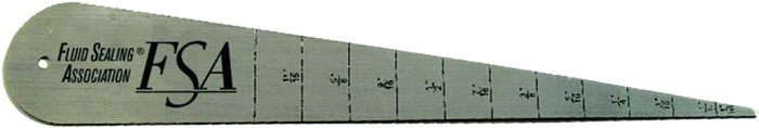 Image 2. Gap Measurement Tool
- Tighten all nuts by hand but do not exceed 20 percent of the recommended torque.
- Round 1: Torque each nut to approximately 30 percent of the recommended torque.
- Round 2: Torque each nut to approximately 60 percent of full torque.
- Round 3: Torque each nut to approximately 100 percent of the full torque.
- Round 4: Apply at least one final full torque to all nuts in a clockwise position until all nuts are a uniform torque.
