

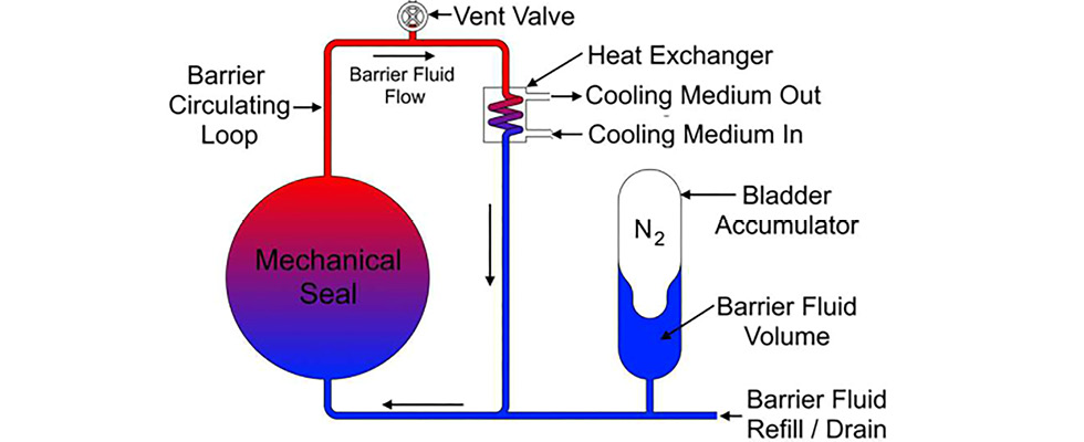
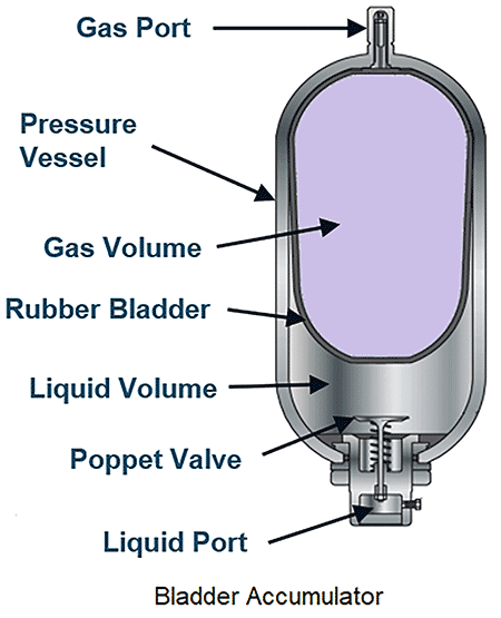
An American Petroleum Institute (API) plan 53B system is a pressurized liquid barrier system connected to a dual pressurized mechanical seal that supplies the seal with clean, cooled barrier fluid at a pressure greater than that of pressure in the pump seal chamber, ensuring zero emissions of the process fluid. A 53B accomplishes this by utilizing a bladder accumulator design to apply pressure to the barrier fluid, along with a heat exchanger to dissipate heat generated by the mechanical seal and absorbed from the pump. A gas (typically nitrogen) is introduced into the bladder at a pressure just below the desired barrier pressure, and as fluid is added to the system, the gas bladder is compressed and pressure will increase.
There are several advantages to a setup like this, including:
- The ability to avoid gas entrainment of the barrier fluid: At higher pressures, gas will begin to dissolve into the barrier fluid, impacting the ability of the barrier fluid to properly lubricate the seal faces as it degasses around the seal faces due to seal frictional heat generation. By separating the gas and the barrier fluid with a bladder, entrainment cannot occur, and the system can operate at much higher pressures than a 53A system, which uses a pressurized nitrogen blanket in direct contact with the fluid.
- The option to operate a dual pressurized seal in a location without a dedicated gas utility: Unlike a 53A system, which requires a hook-up to a constant source gas header, a 53B only requires a one-time pressurization of the bladder, after which the gas pressure source can be removed. This means the system can be filled from a portable gas bottle and can be utilized in remote locations where a gas header may not be available. A 53B can also be used in situations where a nitrogen header may be unreliable, or where the pressure required is higher than the nitrogen header pressure available.
There are some additional operational needs to consider with a 53B. Unlike a 53A, which will operate at a constant pressure due to the connection to the gas header, a 53B’s pressure will vary over time. The barrier pressure will vary due to:
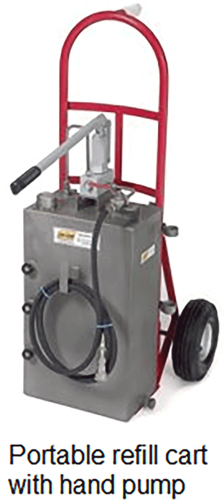
- Barrier fluid leakage: As the mechanical seal leaks barrier fluid, the gas in the bladder will expand, and the pressure will drop. To account for this, 53Bs are operated with a couple of pressure bounds, a high (full set point) and a low (refill alarm) pressure. The system will start at the full set point pressure, and over time it will decay down to the refill alarm pressure, at which point barrier fluid will need to be pumped into the system to bring the pressure back up to the full set point pressure.
- Environmental temperature: As the bladder accumulator is located outside the normal barrier fluid loop, it is not influenced by the temperature of the pump or the barrier fluid. However, it is influenced by the environmental temperature. When it is hot outside, the gas pressure in the bladder will increase. Similarly, when it is cold outside, the gas in the bladder will contract and the pressure will decrease. These pressure swings need to be accounted for when setting the system pressures.
Pressure Set Point Strategy
One of the most important things to consider when using a plan 53B is determining the pressure set points of the system. There are three different pressures to consider: the pre-charge pressure, the refill alarm pressure and the full set point pressure. The pre-charge pressure is the pressure the gas in the bladder is set to. The refill alarm pressure is set at the minimum barrier pressure, and the full set point pressure is what the system gets pressurized to when the barrier loop is refilled with new barrier fluid.
These pressures can vary depending on whether a fixed or floating strategy is used. A fixed strategy implies the pressure set point does not change with ambient temperature, whereas with a floating strategy, the pressure will move depending on the ambient temperature. The pre-charge pressure always uses a floating strategy. Since the pressure of the gas will change with temperature, it is important to alter the pre-charge pressure with temperature so a constant volume of gas can be achieved. Every application that uses a 53B should come with a nameplate that indicates what the pre-charge pressure should be at varying temperatures. When the bladder pressure is being set during commissioning, the ambient temperature of the location where the bladder is being filled should be noted and the chart consulted to determine the correct pressure.
The refill alarm and full set point pressures can use either a fixed or a floating strategy. This means it is possible to have a fixed refill alarm and fixed full set point, a fixed refill alarm and a floating full set point or a floating refill alarm and floating full set point (floating refill alarm and fixed full set point is not a commonly used strategy).
A fixed refill alarm and fixed full set point is the simplest of all the strategies. This strategy is actually not discussed in API 682, but it is the most common one used due to its simplicity. This assigns a fixed value to both pressure set points so an operator knows exactly when to go out and pump fluid back into the system, and at what pressure they should stop refilling the system. The operators themselves do not have to consider what the environmental temperature is. Instead, the environmental temperature is taken into account by the calculation used to determine the refill alarm and full set point pressures. Transmitters are also not needed to coordinate the system pressure set points with the environmental temperature. The downside to this strategy is the need for a higher barrier pressure, and the seal and system need to be designed to handle this higher pressure. With a fixed-fixed strategy, it is also beneficial to use a larger volume accumulator (like a 10 gallon versus a 5 gallon) to help limit overall barrier pressure and the pressure differential between the full set point and refill alarm.
A fixed refill alarm and floating full set point is a bit more complicated, as it relies on knowing the environmental temperature at the accumulator to determine the full set point pressure. If the temperature is lower, the full set point pressure will be lower. If the temperature is higher, the full set point pressure will be higher. A chart will be provided that an operator can consult for the correct full set point pressure at any given temperature. The benefit of using a floating full set point pressure is that it allows for an overall lower full set point pressure, and it does not require any transmitters. The disadvantage is that now an operator needs additional information (environmental temperature) to determine the full set point pressure, introducing the potential for a mistake.
A floating refill alarm and floating full set point pressure is the most complicated strategy, and it relies on the use of transmitters to determine the pressure set points based on environmental temperature. The advantage of this strategy is that the total working volume required is reduced, allowing for a smaller accumulator size. This can also help to reduce overall barrier pressures. However, the initial investment can be costly due to the need for transmitters on the system, and the added complexity introduces more chances for something to fail. Complex programming with the distributed control system (DCS) to coordinate the system pressures is also required.
Tips for Optimal Commissioning & Operation
A properly sized 53B system and the selected pressure points should result in a minimum time between refill of 28 days. Actual time between refill may be higher, as API 682 requires a safety factor of two for the leakage rate when determining the system pressures. Additionally, for an accumulator exposed to atmospheric conditions, variations in time between refill may occur due to changes in temperature and weather. If a system is not meeting the minimum agreed upon time between refill, troubleshooting of the seal and system may be required to identify the issue. This should include verifying the system pressures were calculated with all variables in mind, such as ambient conditions and expected seal leak rates, as well as identifying whether the seal itself is leaking more than expected.
An API plan 53B system, with its minimal utility requirements and installation flexibility, offers an easy to implement and reliable solution for a wide range of applications exceeding the scope of traditional pressurized systems like an API plan 53A. The correct sizing of the accumulator and heat exchanger, together with best installation and operational practices and an effective alarm strategy, are the keys to years of reliable performance from a plan 53B system. For more detailed information on the API plan 53B as well as other piping plans, please visit the Fluid Sealing Association KnowledgeBase at fluidsealing.com.
We invite your suggestions for article topics as well as questions on sealing issues so we can better respond to the needs of the industry. Please direct your suggestions and questions to sealingsensequestions@fluidsealing.com.
