

In boiling water reactors (BWRs), there are reactor water cleanup (RWCU) systems that are designed to maintain a reactor’s water quality by filtration and ion exchange. Water quality is important to minimize corrosion and prevent fouling of heat exchangers within the reactor. This system uses pumps to circulate a portion of the reactor working fluid, typically about 1 percent of the feedwater flow rate, through the filtration system.1
Typically, BWRs were designed and built with coupled end suction pumps that make use of a mechanical seal between the pump shaft and the pump case. Depending on the reactor design, these pumps operate either before or after heat exchangers, with temperatures of the pumped fluid ranging from ambient to 575 F. They typically develop 500 to 575 feet of head at 160 to 500 gallons per minute (gpm) and are designed for 1,400 to 1,420 pounds per square inch (psi).
Problem
The high pressure and sometimes high temperature of this application makes it difficult for traditional mechanical seals to have an adequate operational life. This case study focuses on a nuclear plant that was having mechanical seal failures roughly every three months across its BWRs. In addition to seal failures, these pumps were also having thrust bearing failures from time to time. The plant uses two RWCU pumps per reactor.
The pumps are designed for 1,410 psi at 150 F and develop 500 feet of head at 180 gpm each. The water being pumped through this system is radioactive, meaning the seal and thrust bearing failures require maintenance that exposes workers to high doses of radiation. In addition to radiation exposure and high cost associated with failures, one of the two pumps being offline results in degrading water quality that can get to levels requiring reactor shutdown within days.
Solution
The plant learned that there had been successful implementation of sealless pump retrofits for this at other sites that had been operating without failure or maintenance for more than six years. After reviewing the capital costs against the implications of leakage, both financially, but more importantly based on increased safety, the plant opted to implement a canned motor retrofit of the existing coupled end suction pumps.
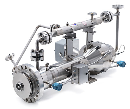
By using a horizontal canned motor retrofit, they were able to keep the existing pump cases and obviate the need for any pipework modifications in the room. Part of the scope of the supply on this project was reverse engineered impellers to match the original hydraulic performance along with custom designed heat exchangers for the canned motor retrofit.
Design
The canned motor pump uses a common motor/pump shaft that is fully wetted and within a pressure boundary rated for the design temperature and pressure per American Society of Mechanical Engineers (ASME) Boiler and Pressure Vessel Code Section III.
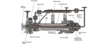
The retrofit consists of five main assemblies: the thermal neck assembly, the motor case/stator assembly, the motor cover assembly, the rotating assembly and the heat exchanger. The thermal neck assembly separates the hot pumped fluid from the cooled motor cavity, where the bearings and motor windings see increased performance and life with lower temperatures.
The motor case/stator assembly houses the motor windings encapsulated in a resin (resin omitted for clarity in Image 1) behind a thin corrosion resistant stator can that is the barrier to the fluid filled motor cavity. It also houses the radial bearings and the seat for the main thrust bearing.
The motor cover assembly provides space for the thrust bearing and houses the reverse thrust bearing, as well as provides a connection point for the heat exchanger pipework.
The rotating assembly consists of a shaft with its electrical components (laminations, rotor bars, short circuit rings) protected from the fluid-filled cavity by a rotor can, as well as plated journal surfaces, a thrust disc and a reverse engineered impeller. The heat exchanger is a shell and tube heat exchanger that transfers heat from the motor’s fluid to an externally supplied cooling water flow.
Features
No mechanical seal
This is the main feature of this design. Having no mechanical seal practically eliminates the chance of leakage or a failure that would result in leakage, increasing the safety of the pump. The canned motor offers double containment, primary being the stator can and secondary the motor case.
Without chance of leakage there is zero ALARA (as low as reasonably achievable) time spent in the room cleaning up reactor circulation water due to pump issues. It also eliminates need for replacement of seal wear parts.
Hydrodynamic bearings
The hydrodynamic bearings are product lubricated and require no external fluid system, reducing the need for auxiliary systems. The main thrust bearing is designed for axial thrust generated by the impeller during typical operation. The rotating thrust disc creates fluid film wedges against stationary tilting pads. Tilting pads, and their spherical seat housing, allow for misalignment correction and stable rotor dynamic operation.
The reverse thrust bearing is designed for off-duty, abnormal operation and startup/shutdown conditions. The rotating thrust disc creates fluid film wedges against the step bearing in the motor cover.
Radial bearings are designed for the weight of rotor, impeller radial loads and unbalanced magnetic pull of the electric motor during operation. Rotating journal surfaces on the rotor create a fluid film against two sleeve bearings.
Hydrodynamic bearings only wear during startup and shutdown, when the fluid film is developing. This allows for increased maintenance intervals when compared to contact bearings.
Auxiliary impeller in thrust disc
Radial holes drilled in the thrust disc act as an auxiliary impeller to circulate motor fluid through the heat exchanger to maximize heat transfer to cooling water through the heat exchanger.
Continuous purge
A continuous purge with nonradiated water allows for continuous flushing of the motor cavity, eventually flowing through the annulus between the rotor and the thermal neck into the process fluid. This allows for a reduction in radiation levels within the motor, leading to a lower dose taken by workers during maintenance.
Stainless steel construction
All wetted surfaces are stainless steel, preventing corrosion within the retrofit
and contamination within the reactor and RWCU system.
Custom design
This retrofit was supplied with a custom-designed sensor package including stator winding RTDs, bearing cavity thermocouples, current transducers, accelerometers for vibration measurement, and a panel with health monitoring software and data storage.
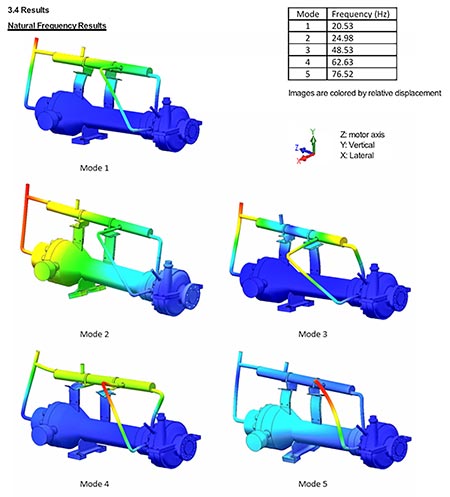
The pressure boundary was custom designed to ASME Boiler and Pressure Vessel Code Section III to the code year of design for the plant, required design pressure/temperature, and required plant seismic loading criteria. A modal analysis for the retrofit is shown in Image 3.
As the original hydraulic loadings were not known, these had to be modeled using computational fluid dynamics. Custom bearings were designed for the radial and axial loading output from computational fluid dynamics associated with the existing hydraulic design. The design ensures that, at the operating temperatures and loading, the bearings operate in the hydrodynamic region and there is rotodynamic stability.
The canned motor retrofit was custom designed to fit up to and use the existing pump case. The existing impeller was reverse engineered using a combination of techniques including 3D scanning and manual measurement to ensure the blade paths were correct.
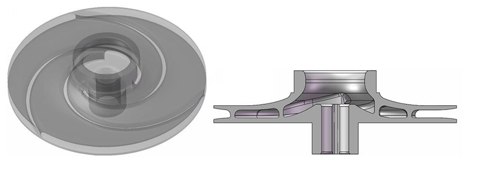
Traditional 3D scanning of impellers can be difficult, given the sweeping vane geometry and blind internal surfaces. This can require the CAD modeler to interpolate geometry that cannot be scanned in the center of the hydraulic passage, causing differences between the model and actual impeller geometry.
Given the importance of the entire hydraulic passage to generate the required duty, a new proprietary technique was used to scan the entire passage and create the model. This new technique is nondestructive and provides data for all surfaces.
The reverse engineered impeller was verified using computer modeling and then during performance testing in the factory. In this application, the reverse engineered impeller was designed to give performance identical to that of the original, but can be custom designed for a different duty point or for entirely new performance.
A 3D model of the reverse engineered impeller for this application is shown in Image 4.
References
1. www.nrc.gov/docs/ML1125/ML11258A313.pdf
