
The late Charlie Jackson, vibration expert at Monsanto, once told me that he was unaware of any centrifugal pump manufacturer that knew how to calculate the hydraulic axial thrust produced within the liquid ends of their pumps. I suspect that he was referring to vendors of single-stage, single-suction pumps because for decades vendors of vertical turbine pumps have seemed to have had a good handle on the thrusts created by their product line. However, I think he was right about the single-stage pump producers. It seems that progress has been limited in that area. I am aware of a number of horizontal and vertical in-line, single-stage, single-suction pumps with thrust bearings that have short lives.
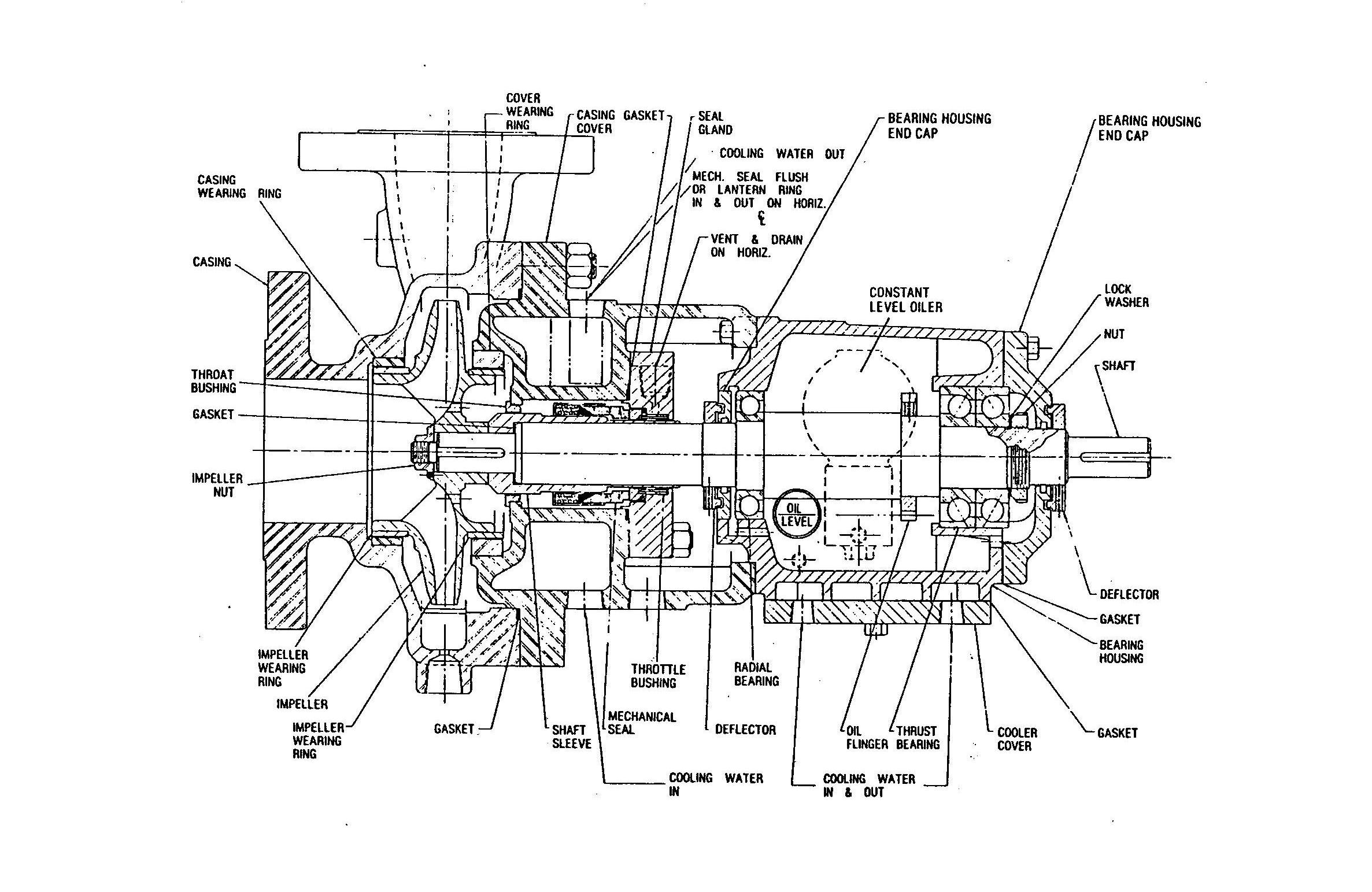 |
| Figure 1. A typical horizontal, single-stage, single-suction process pump with enclosed impeller and wear rings, front and back. |
Horizontal, Single-Stage Pumps in a Refinery
Charlie Miannay was an engineer working for a refinery on the island of Aruba in the Caribbean. He was given the task of determining the cause of, and solution for, the short lives of thrust bearings in a number of the horizontal, single-stage, process pumps in the refinery. Each pump was equipped with a single-suction, enclosed impeller fitted with wear rings on the front and back and with balance holes drilled through the impeller hub (back shroud), which allowed back-ring leakage to flow back into the eye.
The pumps were similar to the one in Figure 1. Examination of the failed bearings indicated excessive thrusts toward the impeller eyes. Miannay knew that increasing the diameter of the back wear ring would reduce the thrust toward the eye and methodically set about increasing the back ring diameters in the problematic pumps. He successfully increased the lives of all the previously short-lived bearings.
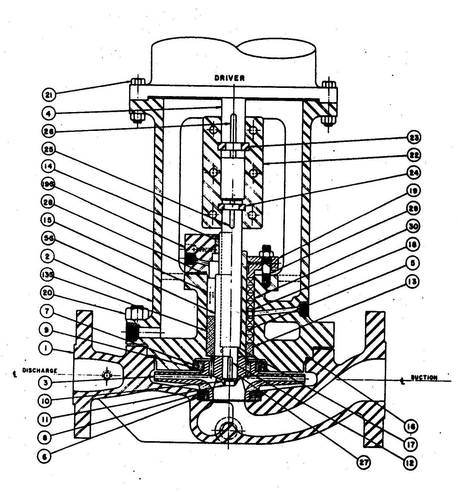 |
| Figure 2. A typical vertical, inline, single-stage, single-suction process pump with enclosed impeller and wear rings, front and back. Courtesey of Afton Pumps |
Vertical Refinery Pumps
I was asked to analyze the short thrust-bearing lives of a line of vertical, in-line, refinery pumps, similar to the one in Figure 2. Each pump had a single-suction, enclosed impeller, with wear rings on the front and back, and balance holes drilled through the impeller hub. The pump shaft was coupled to the motor shaft through a rigid coupling. The axial thrust from the pump was absorbed by the thrust bearing in the motor. The most problematic pump was a 3,600-rpm, 2,000-gallon-per-minute, 600-foot head unit driven by a 300-horsepower motor. The pump was equipped with 7.5-inch diameter wear rings on both the front and back of the impeller.
Even though the 300-horsepower motor was rated to accept a significant thrust from the pump, the investigation revealed that it was equipped with the same size thrust bearing as the 40-horsepower motor provided by that vendor. The axial thrust rating given to the 300-horsepower motor was higher than the 40-horsepower motor, even though it should have been much less, allowing for the extra weight of the motor rotor. That was clearly part of the problem—a wimpy thrust bearing.
A second part of the problem was excessive thrust from the pump. We measured the pressures in the casing all around the impeller, and plugged these numbers into the traditional axial thrust equation from References 1 and 2. When we measured the axial thrust produced by the pump, it was 700 pounds higher than calculated with the equation. (It is no wonder that the over-rated, over-loaded bearing had a short life.)
What was the source of the extra thrust? Could it be from a front shroud running close to the casing? A series of tests was performed with successively smaller impeller outside diameters, and the 700-pound excess thrust did not change. The conclusion was that the extra thrust was being produced within the diameter of the wear rings.
The impeller in this pump was of the Francis design: the vanes twisted as they turned into the eye. This is an excellent design. While it costs more to produce, this design results in higher efficiency and lower NPSHR. Such vanes, though, push the pumpage not only radially but axially. I concluded that it was this axial “push” on the pumpage that created the extra axial thrust. I call this the vane shape or propeller effect. All axial impellers, including inducers, produce axial thrust. The Francis style impeller cannot be excluded from this group.
By increasing the diameter of the back wear ring from 7.5 to 8 inches, the total axial thrust from the pump was reduced to near zero. Figure 3 shows the equation that I produced for calculating the axial thrust of a centrifugal pump. Unfortunately, I have been unable to calculate the value of the propeller effect, so it is necessary to measure the axial thrust produced by each impeller to establish that value.
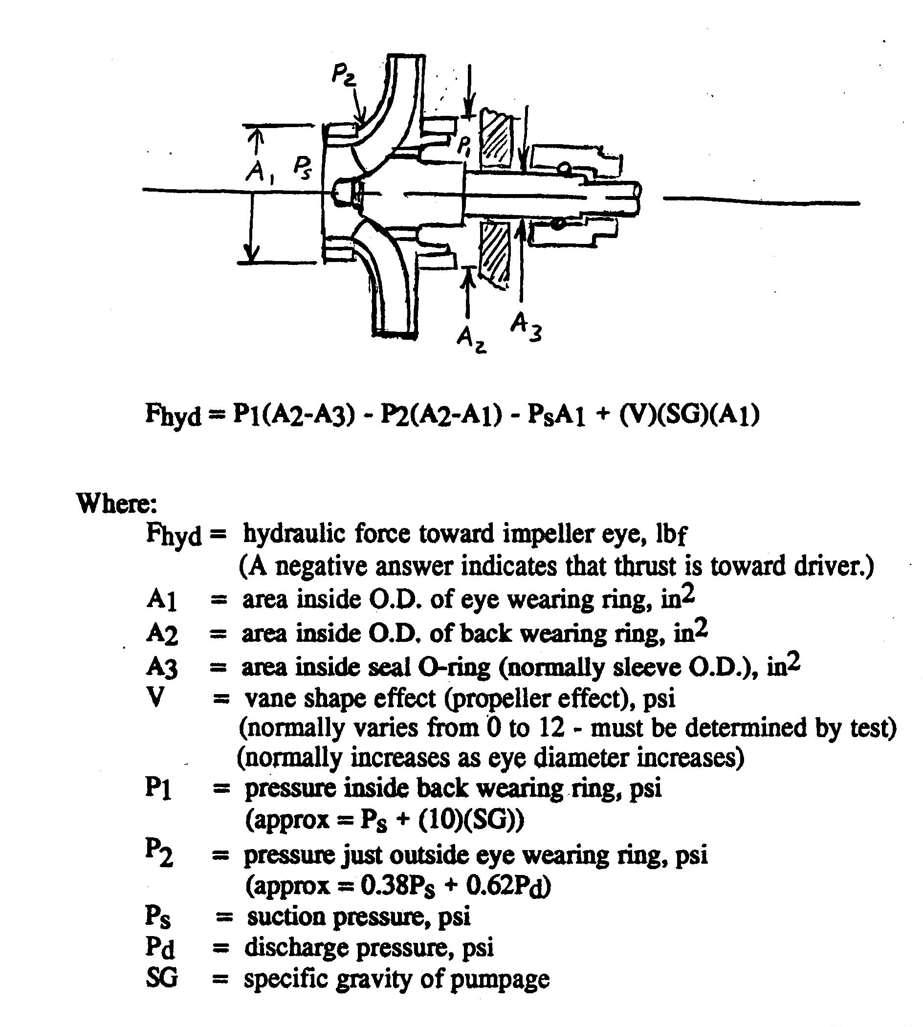 |
| Figure 3. Equation |
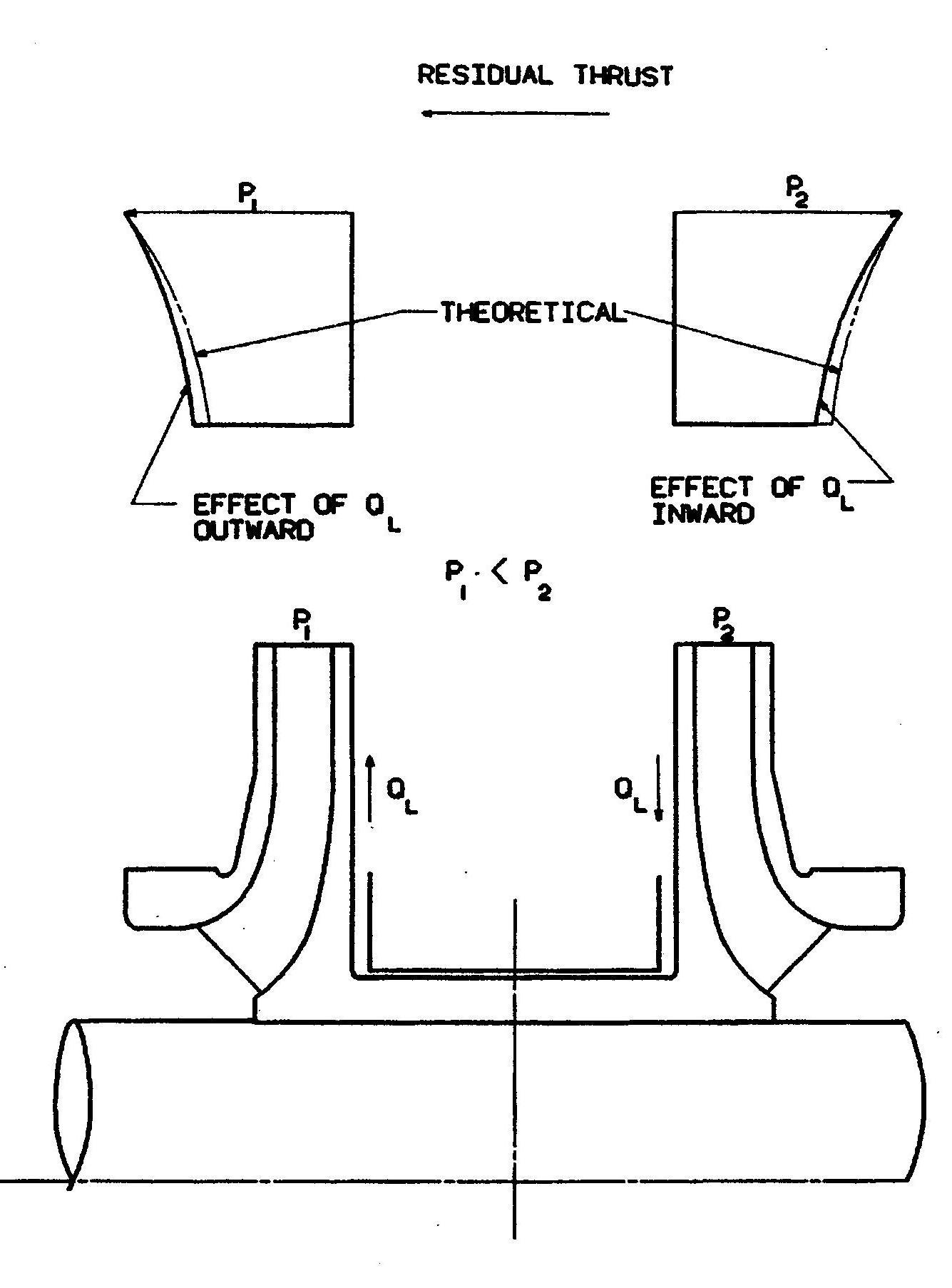 |
| Figure 4. Illustration of axial thrust created by back-to-back impellers. Image provided courtesy of Flowserve Corporation |
The Effect of Wear Ring Clearance
One valuable lesson learned in the testing program was the significant effect that wear ring clearance has on axial thrust. When we increased the clearance between the eye (front) rings, the thrust toward the eye increased significantly, apparently because of the increased strength of the vortex between the impeller shroud and the casing. The conservation of angular momentum caused the increase in the radially-inward flow of pumpage to strengthen the vortex. The higher rotative speed of the disc of pumpage, adjacent to the impeller front shroud, caused a drop in pressure against the shroud, resulting in an increase in the hydraulic down thrust.
The same phenomenon creates an axial thrust in two-stage and multistage pumps with back-to-back impellers. Figure 4 illustrates the principle. The higher pressure impeller is on the right. The higher pressure on its back side pushes pumpage through the center bushing, resulting in an inward flow along the back shroud of the higher-pressure impeller, and an outward flow along the back shroud of the lower pressure impeller.
The lines marked “THEORETICAL” in Figure 4 indicate the pressure profiles for no leakage through the bushing. The flow through the bushing causes the pressure lines to shift to the left for both impellers, reducing the pressure on the back of the higher pressure impeller and increasing the pressure on the back of the lower pressure impeller. Both effects increase the axial thrust to the left. A larger clearance at the center bushing allows more leakage, resulting in higher thrust. Allowing the clearance to increase on the center bushings has been known to cause short lives of thrust bearings.
The extended hubs on both impellers also contribute to an axial thrust to the left.
Charlie, I think that we have made some progress, but we still have a way to go.
References
- Stepanoff, A. J., Ingersoll-Rand, Centrifugal and Axial Flow Pumps, John Wiley & Sons, New York, 1948.
- Karassik, Igor J., Worthington, “Centrifugal Pump Construction”, Section 2.2 of the first edition of the Pump Handbook, edited by Karassik, Krutzsch, and Fraser, McGraw-Hill Book Co., New York, 1976.
- Trout, Robert G., FMC, “Axial Thrust in Centrifugal Pumps”, ASME Paper 62-HYD-13, American Society of Mechanical Engineers, New York, NY, 1963.
