

A centrifugal pump is the most common pump type within the rotodynamic pump family. Centrifugal pumps have a rotating impeller. The liquid enters in line with the shaft and exits the impeller perpendicular (or radial) to the shaft (Image 1, left side).
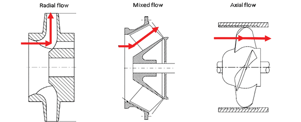
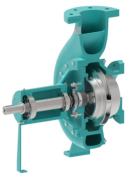
Image 2 is a 180-degree cutaway of a centrifugal pump drawing and shows the impeller enclosed in a casing with inlet
and outlet connections. The casing is designed to direct the liquid into the entrance of the impeller and efficiently collects and directs the liquid exiting the impeller into the system piping. The impeller is driven by a shaft, and bearings carry the radial and axial loads. Lastly, there is a dynamic shaft seal that limits leakage along the rotating shaft. It is attached to a shaft that extends through the power frame.
The impeller and casing are the key hydraulic components in the centrifugal pump. The rotating impeller increases the velocity and pressure of the liquid until it exits the impeller. The casing then efficiently decreases the liquid’s velocity, thereby increasing the pressure. The impeller and casing are designed for peak efficiency at a single flow. This is called the best efficiency point and is referred to as BEP. The pump can operate over a range of flow below and beyond BEP, but the efficiency will decrease.
For more information on centrifugal pumps and other pumps, refer to the Introduction to Pump Fundamentals at training.pumps.org.
