

The demand for electricity is increasing due to the growing population and the electrification of motor vehicles and home heating. Renewable energy is a growing share of the power generation pie, accounting for about 22% of all U.S. production in 2022, according to the U.S. Energy Information Administration. This leaves about 60% of U.S. electricity being generated in fossil power plants and 18% in nuclear power plants, which will continue to serve a large percentage of demand for the foreseeable future.
Legislation has imposed stringent emission controls; therefore, many coal-fired power plants have been retired due to the cost of complying, and newly constructed fossil plants are overwhelmingly combined cycle power plants (CCPPs). CCPPs primarily use natural gas as fuel and can better meet emissions requirements. To keep up with increasing demand and reduced emissions targets, improving power plant efficiency is a very relevant issue, which is supported by applying the appropriate pumps and optimizing pump systems within these plants.
Combined Cycle Power Plant Overview
CCPPs generally consist of multiple gas turbines, which burn natural gas. The gas turbines drive electric generators serving as a portion of the plant’s megawatt (MW) generation. CCPPs also include steam turbine generators that utilize heat recovery from the gas turbine combustion to generate steam. The heat recovery steam cycle increases the efficiency of CCPPs and reduces the emissions compared to other fossil generation plants.
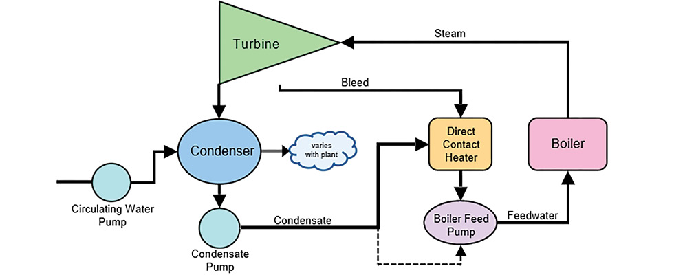
Other than combustion, pumps are the primary source of energy in the steam cycle. Image 1 illustrates a simple steam generation cycle. Condensate is pumped to a heater, and then the boiler feed pump (BFP) forces the water into the boiler at high pressure, where it transitions to high-pressure steam. The steam then drives a steam turbine generator, and finally, the circulating water pump forces large quantities of water through the condenser, which condenses the steam back to water so the cycle can continue.
Pump Application Overview in Combined Cycle Power Plants
A CCPP will typically operate at several load points throughout a 24-hour cycle and may be called on to change load rapidly. When the plant operates at less than full load, the pumping systems will be impacted. Pumps should be selected/specified and controlled to meet the different load points while maintaining optimum plant efficiency and reliability. For operation at reduced load, speed control should be used, when possible, to maintain operation of the pump within the preferred operating region. If load swings are such that the flow rate to the boiler goes below the pump’s minimum flow, a minimum flow bypass line of sufficient size is required to allow the pump to operate reliably.
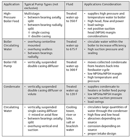
The pump applications within a CCPP can be divided into main service pumps and auxiliary service pumps. There are up to seven pump applications in the main service category and up to 12 pump applications in the auxiliary service category. It should be noted that Image 1 provides a narrow view of pump applications.
Applications within the main service category are listed below with some basic application information and considerations. As noted, the application considerations vary; therefore, the pump types, sizes and configurations will be application specific. The Hydraulic Institute’s Guidebook Power Plant Pumps: Guidelines for Application and Operation goes into full details on all the applications listed, as well as the auxiliary service applications. Within this article, the high-pressure boiler feed application is further discussed.
Boiler Feed Pump Types & Select Design Features
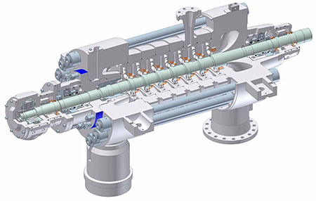
BFPs are the largest pump type with respect to energy used in a power plant. This is due to the high boiler pressure and the large volume of steam that must be generated in the boiler. The boiler pressure can be 3,000 pounds per square inch (psi) or more, which requires a heavy-duty multistage pump that has been designed for this challenging service. In larger CCPPs with higher pressure boilers, the BB4 and BB5 pump types are typically used.
Illustrated in Image 2, the BB4 type is a between bearing, multistage, ring section pump. In this pump type, the sections include an impeller, diffuser and crossover to direct the flow to the next impeller stage. Sealing is accomplished radially by compressing the sections with tie rods under tension. The number of impellers can be increased within limits to accommodate higher pressure requirements.
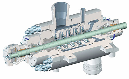
Illustrated in Image 3, the BB5 pump is like the BB4, but it is a double casing design and is often referred to as a barrel pump. Note there is a similar impeller, diffuser and crossover to the next stage, but in the BB5 these hydraulic components are within an outer casing (barrel). This results in pressure containment with a single high pressure radially split sealing joint, which enables the BB5 to be used in the highest-pressure applications.
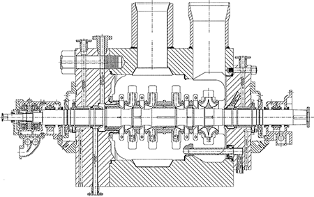
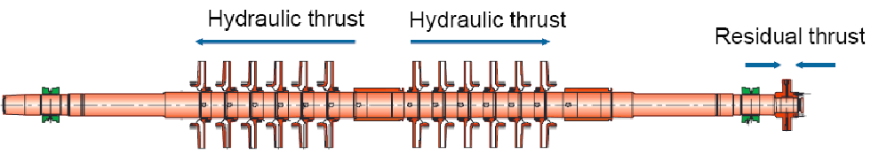
The BB4 and BB5, shown in Images 2 and 3, are both multistage pumps with in-line impellers configuration. The in-line configuration results in additive axial thrust from each impeller. To deal with the axial thrust, a balance drum or disk is used to offset the load, and a thrust bearing supports the residual load. An alternate design to offset the axial load includes opposing impellers, and is available in the BB5 volute type pump in Image 4. In this pump, flow enters on the right side before going through the first two in-line stages. Then, flow crosses over to the third stage on the left side before entering the fourth stage prior to discharging. The offsetting of the axial thrust is depicted in Image 5, which shows the residual load being carried by a thrust bearing. When a rotor is configured with the opposed impeller design, changes in axial thrust overdue to wear in clearances results in smaller residual thrust changes, allowing a smaller thrust bearing to be selected.
Another important design consideration is the pump’s net positive suction head requirement (NPSHr). NPSHr is specific to the first stage impeller, so it is common for the first stage impeller to be a different design than the rest, optimized for NPSHr. The volute type BB5 pump in Image 4 depicts this the clearest, where the first stage impeller is a double suction type that splits the flow to each eye resulting in lower NPSHr.
There are no fixed rules for selecting the pump type for the specific power plant application, and the length of this article only allowed room to highlight a single application and cover limited design considerations. Other important design considerations include materials of construction, shaft sealing, bearing design, lube oil systems, coupling, driver and the pump base and support. For additional information and guidance on pump applications in power generation, applicable pump types and design and application considerations, users are encouraged to refer to Power Plant Pumps: Guidelines for Application and Operation.
