

What are some important considerations when converting an old packed pump to one with a mechanical seal in the chemical process industry?
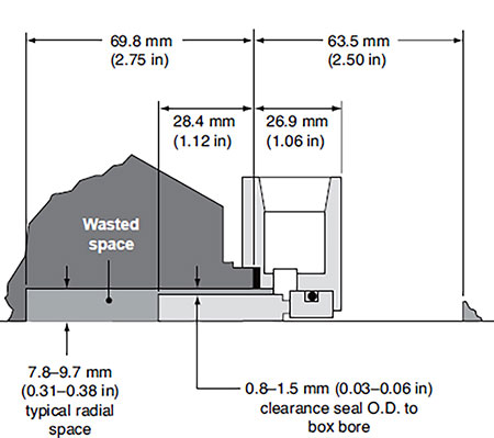 IMAGE 1. Single mechanical seal mounted in a conventional process pump stuffing box (Images courtesy of Hydraulic Institute)
The selection of seal chamber design and seal arrangement is based on requirements to maintain a proper environment for the mechanical seal. Factors to consider include normal operation, startup and shutdown conditions, and standby. Venting of vapors is important where the connection must be at the highest point to ensure a vapor-free condition for the mechanical seal. Various pumps are equipped with seal flush and piping plans based on applications and pump types. Refer to “Hydraulic Institute Mechanical Seals for Pumps, Application Guidelines” for complete information on this topic.
ASME/ANSI B73.1, “Specification for Horizontal End Suction Centrifugal Pumps for Chemical Process,” B73.2 (Vertical In-Line), and ISO 3069/DIN 24 960 Type C specify several seal chamber dimensions for general service pumps. New pump designs or upgrades should comply with those dimensions to maximize the choices of commercially available seal designs already developed and tested for those envelopes.
There has been an effort to upgrade pumps originally designed for packing to accommodate mechanical seals; however, the interchangeability in the conventional stuffing box originally designed for packing results in a compromised mechanical seal design (Image 1).
Generally, there is inadequate removal of seal-generated heat, greater wasted space and overhang, vulnerability of seal damage under off-design pump operation, vulnerability of seal damage from abrasives and seal installation difficulties with dual arrangements.
Improvement 1: Enlarged Cylindrical Bore
An enlarged cylindrical bore seal chamber offers some solutions to the shortcomings of the conventional stuffing box. A typical single seal installed in an enlarged cylindrical bore seal chamber is illustrated in Image 2.
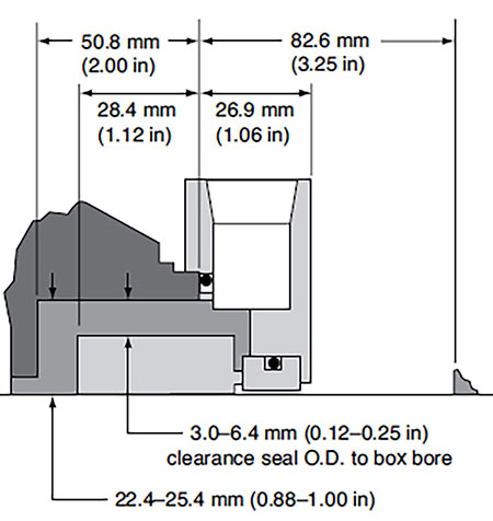 IMAGE 2. Single mechanical seal mounted in an enlarged cylindrical bore process pump seal chamber
This seal chamber design eliminates the wasted space between the seal and the bottom of the seal chamber, provides more radial clearance over the seal outside diameter (OD), and can provide more axial distance outside of the seal chamber for dual seal arrangements.
The enlarged cylindrical bore design offers an advantage to the thermal system. If the radial clearance above the seal is increased to a point where the seal chamber acts more like a large fluid reservoir than an annulus, and the pump throat is enlarged so that fluid can move in and out of the pump casing, then a single seal can perform satisfactorily with no flush.
Improvement 2: Enlarged Tapered Bore
Enlarged tapered bore seal chambers offer the same solutions as enlarged cylindrical bore seal chambers, plus they provide static self-venting and allow more complete process fluid drainage during pump shutdown. A typical single seal installed in an enlarged tapered bore seal chamber is illustrated in Image 3.
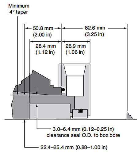 IMAGE 3. Single seal mounted in an enlarged tapered bore process pump seal chamber
Enlarging the seal chamber bore—as shown in Image 3—with a tapered bore results in the low seal face and seal chamber temperatures. This type of seal performance will yield extended seal life. Tapering the seal chamber bore also encourages self-venting of any gases produced within the seal chamber to prevent them from detrimentally affecting seal operating performance.
For more information about seal chambers for chemical process pumps, refer to HI’s “Mechanical Seals for Pumps, Application Guidelines” at www.pumps.org.
