

Every pump application, regardless of how common of a service, has unique sealing solution challenges. The sealing solution for any given pump application rarely has a universally accepted solution and more than likely has multiple solutions offering similar operating reliability. Individual plant location guidelines, governmental requirements, operator preferences or available plant resources must be considered when deciding which sealing solution is the best fit for an application.
The selection of a mechanical seal for pump applications is primarily dictated by the application conditions, typically defined by the equipment design, operating speed, process fluid, process pressure and temperature. When selecting a sealing solution, operators must also consider the plant’s available resources, safety concerns, service reliability and life cycle operating costs to determine the best solution for their application. Boiler feed pumps at fossil fuel power generation plants are a great example application to review what goes into selecting a sealing solution.
Boiler feed pumps move hot water (100 C to 200 C/200 F to 400 F) at moderate pressures (20 to 48 bar/300 to 700 pounds per square inch [psi]). The application’s process conditions allow multiple sealing solutions where each solution can offer years of reliable operation. The pump’s operating pressure at the mechanical seal location typically eliminates the ability to use metal bellows mechanical seals, and the process temperature of the boiler feed water in the pump’s seal chamber is near the limits for elastomeric O-ring secondary sealing elements used in pusher (spring energized) mechanical seals.
A single pusher mechanical seal is the typical sealing solution for boiler feed pump applications, but they require a seal support system to alter the conditions in the pump’s seal chamber to create a more hospitable environment for the mechanical seal. Seal support systems, or piping plans for boiler feed pump applications, are designed to reduce the temperature in the seal chamber to ensure the mechanical seal’s elastomeric O-rings will function reliably and the water process fluid can provide adequate seal face lubrication. To reduce the temperature in the pump’s seal chamber, either a cool external fluid is injected into the seal chamber or the process fluid in the seal chamber must be cooled directly.
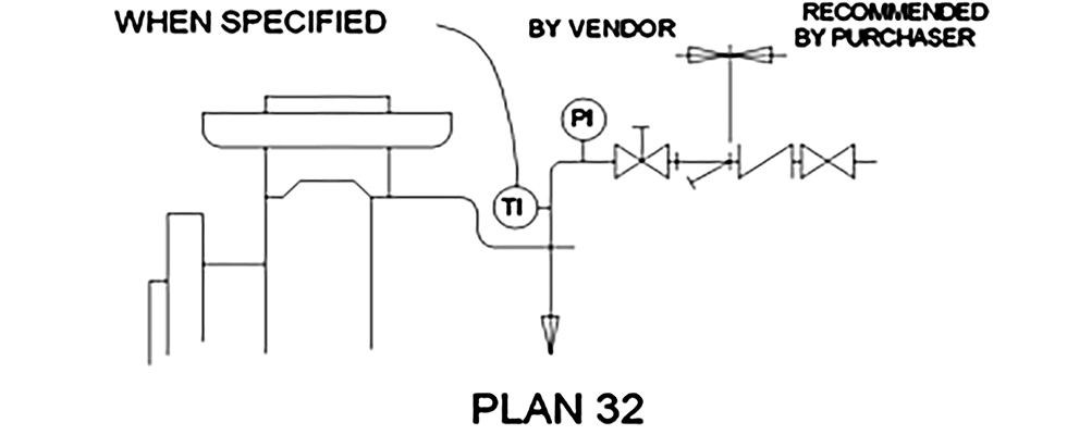
Cooling the seal chamber by injecting an external fluid into the seal chamber is described as an American Petroleum Institute (API) Plan 32 piping plan. For a Plan 32 flush to function properly, the injected fluid must be compatible with the process fluid, be at a pressure greater than the process’ pressure and must be at an adequate temperature for cooling. Additionally, a restriction device, typically a bushing in the throat of the seal chamber, is required to maintain back pressure within the seal chamber and control the flow of the injected fluid out of the seal chamber. To ensure there is no disruption in cooling, the Plan 32 flush must be from a readily available source, preferably a clean, downstream process within the plant.
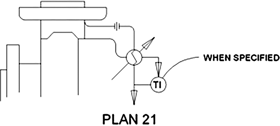
Another method of cooling the seal chamber involves directing a flow of process fluid from the high-pressure side of the pump, typically from pump discharge, through a seal cooler (typically a water-cooled shell and tube style heat exchanger) before it is injected into the seal chamber. This seal support system is referred to as an API Plan 21 piping plan, and it uses the pressure differential between the pump discharge and seal chamber to generate flow through the piping plan. Like the Plan 32, a Plan 21 uses a restriction device in the throat of the seal chamber to isolate the seal chamber from the process fluid and to control the flush flow rate exiting the seal chamber. The Plan 21 seal cooler requires a continuous flow of clean cooling fluid to remove heat from the process fluid prior to injecting it into the seal chamber.
Seal chamber cooling can also be achieved using an API Plan 23, where process fluid is recirculated between the seal chamber and a seal cooler. A pumping device within the seal is required to generate flow through the Plan 23 loop, and like the Plan 21, the seal cooler requires a continuous flow of cooling fluid to remove heat from the process fluid. In a Plan 23, there is no pressure differential between the seal chamber and process to create flow, but an isolation device is used in the throat of the seal chamber to minimize process fluid interchange between the hot process in the pump and the cooler process fluid in the seal chamber.

Knowing each piping plan has different operating requirements, it is important to review how each plan affects the pumping system and its associated operating costs. Short-term costs are often easily seen in the costs to implement the piping plan and include such things as the cost to purchase the seal cooler, throat bushings, mechanical seal modifications and the labor to install. Long-term costs are not always easy to see, as they are typically power requirements. A lot of power is consumed in boiler systems maintaining the process water at operating temperatures. Heat soak is a long-term operating cost referring to the power consumed to overcome thermal losses from the system to maintain its operating temperature.
The Plan 21 in the example boiler feed pump application has a continuous flow of hot water being pulled from the discharge of the pump, cooled in a seal cooler and then injected back into the process. The cooling water required to operate the piping plan is a direct long-term operating cost. The hidden operating cost is the heat soak from the cooled flush being injected into the process. Analysis of a Plan 21 (and all other reviewed piping plans) in the Fluid Sealing Association’s life cycle cost (LCC) estimator calculates the annual cooling water (direct) cost to be $800, while the total annual cost to operate the Plan 21 is $24,640. The total annual cost accounts for the 86.3 kilowatts (kW) of power required to overcome the heat soak losses.
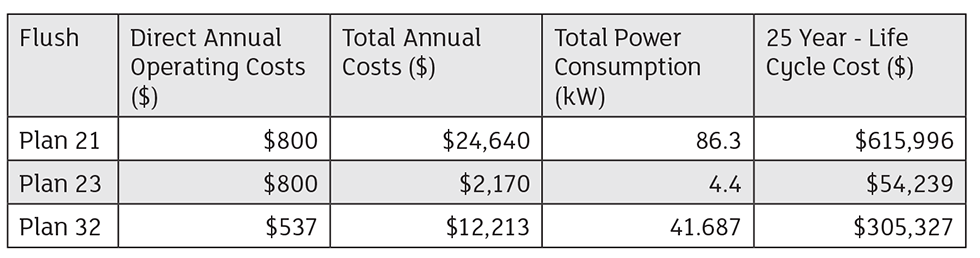
A Plan 23 circulates process water in a loop between the seal cooler and seal chamber. Using the same seal cooler and cooling water flow rate as the Plan 21, the annual cooling water costs for the Plan 23 is $800. However, because there is minimal intermixing of hot process water into the seal chamber, the heat soak power requirements are notably less than the Plan 21’s heat soak—4.4 kW versus 86.3 kW. This low heat soak reduces the total annual cost to operate the Plan 23 to $2,170, a 91% reduction of the cost to operate the Plan 21.
Injecting the Plan 32 external flush of cool water into the seal chamber of the same boiler feed pump application has the lowest direct cost for cool water consumption at $537. This cost is lower because the cool water flush is injected directly into the seal chamber and requires a lower flow rate to provide adequate cooling than the cooling water flowing through the seal cooler in both the Plan 21 and Plan 23. The direct injection of cool water into the seal chamber requires 42 kW of power to offset the heat soak and accounts for a total annual cost of $12,213. This operating cost is half that of the Plan 21, but more than five times that of the Plan 23. These cost calculations assume the Plan 32 flush source is at a sufficient pressure above the process pressure.
Comparison of the total annual costs calculated in the Fluid Sealing Association’s LCC Estimator of the three seal flush plans (Table 1) show the Plan 23 is the least expensive flush plan to operate due to it being the most thermally efficient with the least heat soak. The Plan 23 does have physical constraints, and some pumps do not have the axial or radial space to accommodate the required seal chamber throat bushing and pumping device needed for this flush plan to operate effectively.
The Plan 21 is the least thermally efficient flush plan, making it the most expensive to operate, but only requires a seal chamber throat bushing and does not require any flow modifiers added to the mechanical seal. This makes the Plan 21 an option in pumps where a Plan 23 may not fit. The Plan 32, as analyzed in this example, is the median operating cost flush plan, and like the Plan 21, only requires a bushing in the throat of the seal chamber, allowing it to fit in most pumps. Note the Plan 32 calculations assume the external flush supply is at a sufficient pressure that does not require the additional cost to operate a pump to boost the Plan 32 supply pressure.
When working with a seal vendor to select the best sealing solution for an application, it is best to review not just the application’s normal operating conditions, but should include relevant application of conditions, any local plant guidelines, governmental emissions requirements and the available plant resources required for different seal support piping plans. Knowing all the available resources to support the sealing solution will allow a better review of the possible solutions, which will lead to an efficient sealing solution that will operate reliably throughout its lifetime.
We invite your suggestions for article topics as well as questions on sealing issues so we can better respond to the needs of the industry. Please direct your suggestions and questions to sealingsensequestions@fluidsealing.com.
