

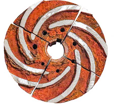
 IMAGE 1: Corrosion damage on the surface of a cast iron impeller after seven years of maintenance. The top and middle images show the external surface; the bottom image shows the internal surface. (Images courtesy of the author)
The majority of water supply systems could have been stopped without preserving them due to the coronavirus lockdown in early 2020, as was discussed in the article “COVID-19’s Effect on Large Buildings” published in Pumps & Systems magazine in June 2020. It is common knowledge that cast iron pumps are widely used in water supply systems. The process of conveying hot and cold water leads to severe corrosion of cast iron impellers and casings. But how may strong cast iron pumps be affected by leaving them in stagnant water for a couple of months due to the lockdown?
In this article, a cast iron impeller is taken as an example to find the answer to this question: How does stagnant water corrosion affect pump efficiency? The cast iron impeller had been conveying hot water at 70 C (158 F) during seven years of maintenance (Image 1). The maintenance schedule was not specified, but the pump had been stopped for half a year without preserving it.
The internal surface of the cast iron impeller shows that the channels between the vanes are severely damaged by corrosion (Image 1, bottom). The corrosion fouling could occupy small parts between the vanes. In this case, the head may be slightly decreased. Unfortunately, the corrosion fouling could occupy the whole space between the vanes, which means that one of the channels would be not included in the processes of water conveying. This would result in the considerable decrease of head and flow. The way flow and head may decrease due to the corrosion damage can be shown in a pump performance curve (Image 2).
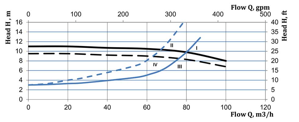
Pump Operating Point I represents the state when an installed pump is new and there is no corrosion damage in the pipelines. If pipelines are worn and corrosion fouling occupies a significant part of the pipelines, then less flow may be conveyed through the pipelines. If flow losses increase due to the pipeline’s wear, the pump operating point will move to Operating Point II.
If a cast iron impeller is damaged by corrosion, it may lead to a considerable decrease of flow and head. A theoretical image of an impeller with velocity triangles will help users understand how different velocities are connected with each other and how corrosion damage causes pump efficiency to decrease (Image 3).
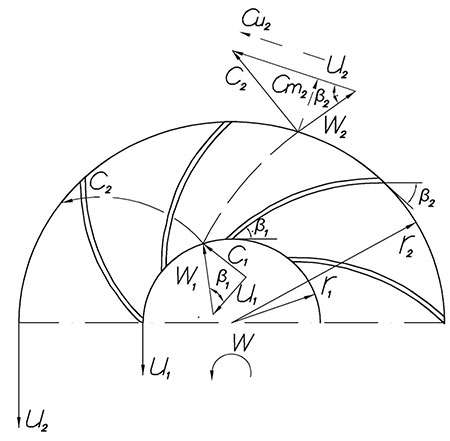
The u1 and u2 are peripheral velocities of impeller blades at inlet and outlet. Flow enters the impeller at a c1 velocity and at a radius r1and leaves it at a c2 velocity and at a radius r2. The c1 and c2 are absolute velocities. The blade design forces the relative velocity, i.e., the velocity that is experienced by an observer traveling with the blade movement, to alter its magnitude and direction from w1 to w2. The absolute velocity consists of tangential cu and radial cm velocities.
Equation 1
The theoretical head may be calculated using Equation 1 if flow enters the impeller when cu1=01.
The head depends on peripheral velocity u1 and tangential cu2. If cm2 increases and the β2 angle remains the same, the velocity vector cm2 will move to the left from its initial position (Image 3). It is possible that if a pump works under operating conditions that are different from initial startup, that this will lead to a decrease of cu2 and head.
The theoretical cm velocity may be calculated using Equation 2.1
Where: Q = flow (gpm, m3⁄s)
r = impeller radius (meters)
b = weight between impeller vanes
Equation 2
As the weight b between vanes decreases, the cm2 velocity increases (see Equation 2) and this leads to head decreasing (see Equation 1).
If corrosion fouling occupies a significant part between the impeller vanes, it leads to a decrease of head and flow (Image 2, Operating Point III). If there is corrosion damage inside the pipelines and a cast iron pump, the operating point will move to Point IV. If the whole weight between vanes is occupied with corrosion fouling, it means that the whole channel will not be included into the process of operating conveying liquid.
Actually, so many centrifugal pumps are oversized and even significant decrease of head and flow cannot affect the system in which they are installed. Nevertheless, there are many applications where even a slight decrease of pump efficiency may result in considerable financial loss. Cast iron pumps are widely used in different cleaning services, such as railcar or oil depot cleaning services. If it takes longer to clean one railcar, it means that the cleaning of all other railcars will be slowed down correspondingly. All cleaning processes at petroleum terminals are scheduled, and if it becomes necessary to clean an oil depot for longer, it means that a petroleum terminal will stay without one depot.
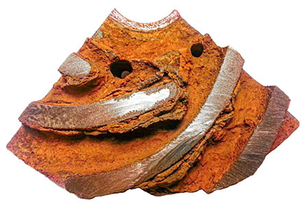
 IMAGE 4: Impeller vanes
Many railcar or oil depot cleaning schedules have been rearranged due to the COVID-19 pandemic lockdown, and cast iron pumps used for cleaning services could have been left in the pipelines filled with water. The pump used as the example in this article had been stopped for half a year. This may prove why some of the impeller channels show considerable corrosion fouling between the vanes.
It is hardly possible to predict when malls, hotels, business centers and stadiums will be fully open again, but measures to prevent corrosion and microbial growth in water supply systems should be taken before shutting down piping systems becomes necessary. Otherwise, such problems as microbial growth and corrosion may surface, which leads to the decrease of pump efficiency.
Reference
1. “Handbook of Pumps and Pumping” by Brian Nesbitt, 2006
