

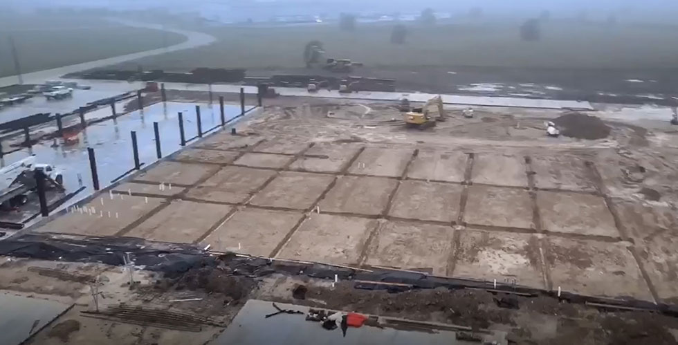
IMAGE 1: Performance test field layout (Images courtesy of KSB SupremeServ)
Centrifugal pumps are an essential technology used to move fluids for numerous applications across all industries. The ability to validate pump performance, efficiency and reliability is a requirement of many published standards, such as American Petroleum Institute (API) 610 and procurement specifications for new equipment. The need for performance test fields (PTF) to support the aftermarket has increased in recent years as unit operators seek to extend the life or upgrade the output of existing equipment. The availability of these facilities to support these process improvements is limited. Recently, a new service center was being built in Texas, and a PTF was incorporated in their design. This PTF was essential at this service center to support providing reverse engineering, retrofits, hydraulic upgrades and drop-in replacements they engineer and manufacture.
The first step in designing a PTF for centrifugal pumps is to determine the required specifications, such as the specifications from the Hydraulic Institute, and the pump style, such as horizontal or vertical. Additional specifications include the flow rate range, pressure range and associated horsepower (hp) requirement. These specifications will bracket the size and type of pump that can be tested. Once the specifications are determined, the design process begins.
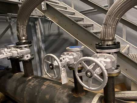
The PTF must be designed to simulate the conditions in the operating system as closely as possible. While the PTF layout will be somewhat simplistic, as illustrated in Image 1, the design requires many different engineering disciplines, from mechanical, electrical and civil to instrumentation and controls logic. Piping systems must consider not only flow control valves, but also isolation valves, straight runs for flow meters, header supports, high point vents, low point drains, etc. The location of instrumentations to capture pressure and temperature must be considered, and the routing of the data cables to the central control room and data logger must be clean and free from any signal noise.
The foundation system needs to be designed to measure the pump vibration accurately, and a rigid foundation laid on a site with proper backfill and isolated from the surrounding environment is critical. Crane capacity and/or forklift access are essential to moving the drives and pumps to their proper locations.
The electrical system design must have the appropriate voltage and amp loading to drive the required motors. Older PTFs typically used a fleet of motors and gearboxes to facilitate the coverage of the vast array of pump operating speeds. Modern PTFs leverage variable frequency drives (VFDs) to reduce the number of motors, eliminating the need for gearboxes and reducing the cycle time required to swap pumps being tested. Designing a modern PTF from scratch facilitates the ability to size the electrical drive system to a higher capacity, whereas older facilities are forced to conduct a reduced speed test or simply cannot test. While some industry standards accept reduced speed testing, the ability to test the pump at the true service duty point and rotations per minute (rpm) is the preferred method.
All of these design elements must be pulled together to establish the physical layout of the PTF facility. While the PTF loop itself is simplistic, users will see crosschecking the design with all the technical disciplines is an important and imperative task. A misstep or oversight in the design may produce major delays in construction and budget overruns.
Constructing the Performance Test Field
Once the design is complete, the PTF can be built. To have a modern-day PTF, special consideration to the site foundation must be made to ensure the quality of the test results. The above-mentioned service center was prepared first by clearing the site of vegetation and surface soil. Then the site was proof-rolled with a pneumatic-type roller to detect any remaining weak areas. Once the weak areas were removed, the site was backfilled to grade per the design specification with properly engineered compression and leveling.
Next, all underground mechanical, electrical and piping were routed and tested for leaks. The building grade beams and column footers were dug, and all reinforcement steel was set. Specialty foundations were sectioned off, and the master forms were placed. Then, everything was set to pour the concrete.
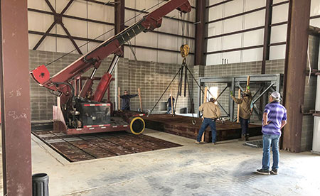
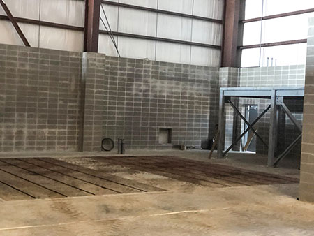
The design included two steel machine tables, each set inside the cast pockets of the isolated foundation. The machine tables provided “T” slots to use for mounting the motors and the pumps. The tables were leveled and grouted in place. Images 3 and 4 show the tables being set in their concrete pockets.
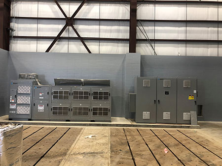
VFD technology was also chosen to be included in the design. A master switch gear had to be installed to take the line voltage and be able to route it to the 4,160 volt (V) or the 480 V transformer. Then, the electrical feed from the 4,160 V transformer was routed into the VFD, capable of 5000 hp, on the left in Image 5. The 480 V transformer was routed into the VFD, capable of 1,000 hp, on the right.
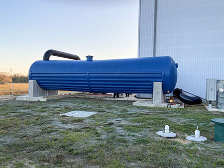
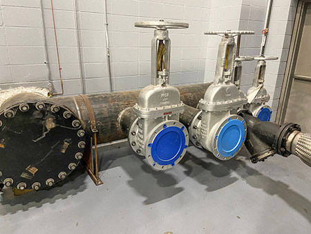
A railcar was repurposed for water storage, and the piping header to and from the railcar was 24 inches. Again, a foundation system must be designed and cast to support the storage tank. The suction and discharge headers were designed and constructed with various sizes to facilitate different flow requirements. A “Y” strainer was used on the suction side to protect the pump from possible foreign object damage, and a flexible stainless steel pipe was used to tie into the suction and discharge straight runs upstream and downstream of the pump.
Designing and building a PTF for centrifugal pumps is a complex process that requires careful planning and attention to detail. Good project management will help users successfully complete the PTF and identify barriers along the way. Starting up and testing the PTF system is also essential to ensure it functions properly within the original design specifications after construction is complete. By following these steps, a reliable and efficient PTF can be achieved.
