

A chemical processing plant had been experiencing high vibration and bearing failures on their furnace water circulation pumps. This application uses a sealless combined pump and motor, due to the high pressure and high temperature water being circulated. This vibration and wear required that the motors be overhauled approximately once per year at a cost in excess of $100,000. These issues had been occurring since the pumps were first installed in the late 1990s. Investigations after initial commissioning of the units indicated that the vibration frequency being measured, 177 hertz (Hz), also matched the first bending mode frequency of the rotor; however, the phenomenon which excited this mode was not conclusively identified.
The leading theory at the time was that the bending mode was being excited by the stator slot to rotor bar passing frequency. Eliminating this forcing frequency would require a redesign of the shaft to change the natural frequency or a redesign of the stator and rotor to change the slot pass frequency. Therefore, the decision was made by the chemical processing plant to leave the design as-is and accept that the motors would require frequent repairs.
Eventually, new personnel took over the management of these pumps at the plant and decided to reopen the investigation into the vibration issue. Engineers were asked to assist in the root cause analysis. The investigation started by examining the effect of a 90-degree elbow in the suction line immediately upstream of the pump suction flange. Given the proximity of this elbow to the eye of the impeller, the hypothesis was that this elbow was causing flow-induced vibration at the frequency being detected at site (177 Hz).
The engineers imported models of the pump into computational fluid dynamics (CFD) software to analyze the effect of the suction elbow. Two models were constructed, one with the 90-degree elbow and one with a straight pipe inlet to the suction flange. Both models had identical pump cases, impellers and diffusers.
Simulations were performed at several flow rates at and surrounding the main duty point. Results were evaluated for indications of flow induced vibration, such as pulsations in the discharge pressure and/or pulsations in axial or radial hydraulic loads. Interestingly, all of the models showed a distinct pulsation in radial load which occurred at exactly 177 Hz. The magnitude of this pulsation was unaffected by the presence of the elbow, effectively eliminating it as the root cause of the vibration. These simulations also showed that the cause of the vibration was driven hydraulically by a phenomenon within the pump itself and that the vibration was not being caused by the motor or elsewhere in the piping system.
This led to a thorough review of the existing hydraulic design, specifically focused on the impeller and diffuser blade combination. This was a custom hydraulic design created specifically for this application. This design used a mixed flow 6-blade impeller and a radial 7-blade diffuser. This combination was likely originally chosen based on the simplistic practice of adding one more blade to the diffuser than is present in the impeller.
A review of hydraulic design literature, specifically “Centrifugal Pumps” by Johann F. Gülich, indicated that this 6- and 7-blade combination was to be avoided because it would often result in nonzero hydraulic radial load and cause lateral vibrations at the impeller blade pass frequency, which in this case is 177 Hz. The impeller blade pass frequency is calculated as the impeller blade count multiplied by the running speed of the pump (1,775 rotations per minute [rpm]). Because the first bending mode frequency of the shaft is also 177 Hz (based on results from the early post-commissioning tests), this mode is excited by the hydraulic radial load, which causes the high vibration measured at site.
The CFD data was further processed to plot the behavior of the radial load vector versus time. This showed that the radial load oscillated in a pendulum-like nature with a swing of approximately 120 degrees. The frequency of this oscillation was 177 Hz. Not only did this radial load oscillation excite the bending mode of the shaft, but it also likely disrupted the formation of the fluid film within the journal bearings, leading to accelerated bearing wear and premature bearing failure. In order to eliminate this oscillating radial load behavior, the diffuser or impeller would need to be redesigned with a different number of blades. Because the impeller was meeting the desired performance, and a redesign would require performance testing and trimming, the diffuser was the obvious choice for the redesign.
Following the guidance of Gülich, a 6-blade impeller could be paired with either an 8-blade diffuser or a 10-blade diffuser. These combinations are not likely to cause vibrations at the blade pass frequency and will therefore not excite the bending mode of the shaft.
The decision was made to use an 8-blade diffuser because this would add less surface area compared to the 10-blade diffuser, and therefore, overall pump performance would be closer to the original pump performance (in terms of head and efficiency). This was a key consideration for the plant, as they did not want to change the duty head and flow of their system.
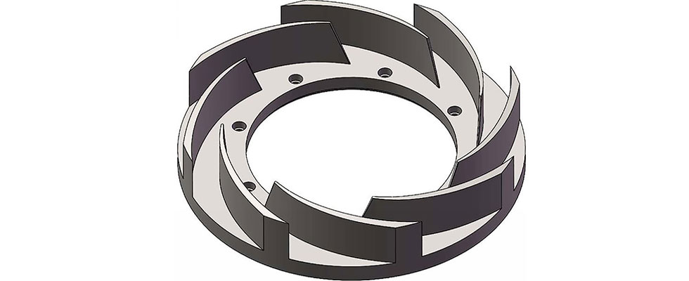
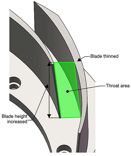
The design of the 8-blade diffuser (Image 1) was based heavily upon the design of the original 7-blade diffuser, given that the blade angles were well matched to the impeller. In order to minimize detrimental effects to pump performance, the combined throat area of the blade passages for the 8-blade diffuser would need to match that of the original 7-blade diffuser. To compensate for the additional metal now in the flow path, the blades were thinned slightly (by 0.075-inch), and the height of the blade passage was increased slightly (by 0.020-inch). This ensured that the combined throat area did not change, and therefore, the flow was not unintentionally restricted by adding the eighth blade (Image 2).
A CFD model was created with this new 8-blade diffuser. Other than the new diffuser, this model was identical to the one used for the original evaluation.
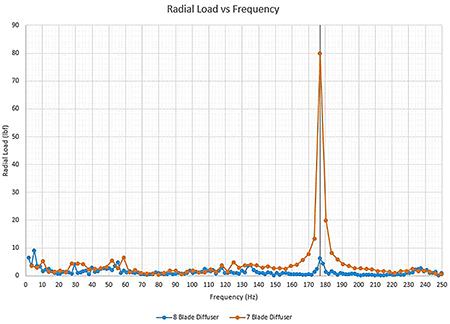
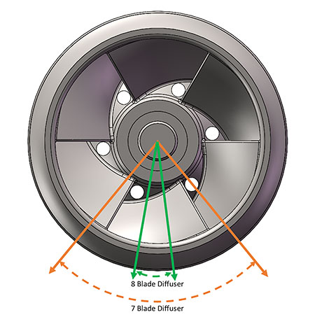
This simulation showed that the radial load magnitude, which occurred at 177 Hz, had been reduced by 92%, indicating that the oscillating behavior had been eliminated (Image 3). A plot of the radial load vector versus time confirmed this; the load now acted in a near constant direction with only slight variations in direction occurring randomly rather than at a constant frequency (Image 4). Because this load acted in a near-constant direction, it would not excite the shaft natural frequency, and it would allow the fluid film in the journal bearings to become fully established. This would result in extended bearing life.
Based on the results from this simulation, the chemical processing plant purchased one diffuser to be installed during the next pump overhaul to validate the CFD prediction that the vibration would be eliminated. This diffuser was fully computer numerical control (CNC) machined in-house and was installed in the pump. The user took vibration readings after the pump had been installed and energized and confirmed that the 177 Hz vibration had been eliminated. They subsequently purchased two more diffusers so that all three pumps would have the new configuration.
Because these new diffusers have eliminated the high vibration and excessive bearing wear, the frequency of the motor overhauls will be greatly reduced, needing to be performed at most once every seven to eight years, saving over $3 million over the life of each motor.
Overall, this project took less than two months from the time the initial models were created to investigate the suction elbow, to the time the machining drawing for the new diffuser was released for manufacture. The total cost of this project, including the three new diffusers, was less than the cost of one motor overhaul.
