

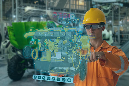
IMAGE 1: A digital twin model of a typical fluids piping system. The calculated pump discharge pressure of 91.71 pounds per square inch gauge (psig) will be compared to the as-operated value to validate that the model of the physical system is accurate. (Images courtesy of the author)
It seems that new technologies burst onto the engineering scene every few years, spurring articles in the technical press about how such cutting-edge solutions will change the world of manufacturing—or even the world itself. It’s tempting to dismiss these phenomena as buzzwords, but it’s worth noting that, almost always, the relentless advance of technology really does change the landscape after the wave of media coverage subsides. What’s more, these changes can truly make a difference in the design, operation and maintenance of assets like fluids processing systems.
Digital twin is the breakthrough technology-of-the-moment. In fact, my most recent columns for Pumps & Systems touched on it; last time, in December 2020, I addressed the question of what a digital twin for a fluids processing system is designed to do.
In this article, I’ll offer greater context into the digital twin, and why elements of that breakthrough environment are already providing insights into the operation of physical systems. Because the digital twin is part of the Industry 4.0 movement, it’s part of a constantly evolving transformation that harnesses the advancing state of the art in cloud computing, for example, or low-cost sensors and instrumentation. That’s why I think of it not as a destination in itself, but as a journey toward optimizing the entire life cycle of a fluids system.
The Digital Twin Within Fluids Processing Environments
Digital twin technology has been applied in many industries with common challenges: costly assets; long life cycles; the need for interaction among multiple disciplines; large fleets of common physical assets; and financial penalties that result when systems fail to meet operational goals. The aerospace industry was one of the first to implement digital twin technology. In recent years, it’s been embraced by owners of combined cycle turbines, locomotives, fleet trucks and compressor stations—just to name a few. Now the digital twin is being used in industrial, commercial and municipal facilities throughout the life of fluid piping systems.
It’s worth remembering that all digital twins simulate the operation of a physical system and provide insight throughout the life of the facility. It consists of four basic elements:
- a mathematical model describing the system
- industry-specific data about each item of equipment making up the system
- values from installed instrumentation within the facility
- methods to analyze the calculated values to gain insights into the operation of the physical systems
The system mathematical model is based on a resource balance—the principle that the resources going into the system are equal to the resources consumed by the system. The mathematical model portion of the digital twin is usually a computer modeling and analysis application (CMA). The application selected varies based on where and how the digital twin is being applied; it can be a chemical process simulation, a thermal analysis, a
stress analysis, a financial analysis or a fluid analysis.
A facility is made of multiple systems working together to make a product or provide a service. As a result, the digital twin of a facility is made of multiple threads each being used to deliver system insight, along with insight on how each thread affects the total system.
Insights Into the Life of a Piping System
Let’s look at a fluid piping system (Image 1). The mathematical model for fluid piping systems is based on an energy balance—specifically, that the energy added to the fluid by the pump elements equals the energy consumed by the process and control elements. The industry-specific data from the physical piping system is entered into the model. Information such as pump curves, control valve coefficients, process losses as a function of flow rate and equipment elevations helps build the model. Since the digital twin is intended to last the lifetime of a facility, it’s important to use current, as-built data when modeling the system.
Once the model is created, the as-operated values are entered. This consists of the energy at the system boundaries based on the tank and vessel levels and pressures, controller set points, position of isolation valves, operating pumps, etc. With the as-built and as-operating data entered, the CMA performs an energy balance for the model. The calculated model provides a wealth of system information, including the balanced pressures and flow rates for each system element.
Now, the calculated results from the CMA application must be validated against the actual operation of the physical piping system; to do that, compare the as-measured values from the installed plant instrumentation with the as-calculated values of the model. For example, in Image 1, the calculated pump discharge pressure is 91.71 psig; with the as-measured value of the pump discharge pressure gauge reading 92 psig, the model is validated. It can be further validated by comparing the as-calculated valve position of 60.42% open with the observed value of the valve position of 60% open.
With a valid model, the digital twin is able to give users greater insight into system operation. This can be in the form of calculated “virtual” values such as flow rates and pressures, along with more involved calculated values.
For example, in Image 1, it calculates the flow rate through the pump and the pump suction pressure, along with the net positive suction head available (NPSHa) at the pump suction. Since the manufacturer’s supplied pump curve is part of the model, the digital twin can determine if pump cavitation is occurring if the NPSHa is less than the manufacturer’s specified net positive suction head required (NPSHr).
Taking a Digital Twin Journey
The digital twin’s mathematical model is constrained by physics and engineering principles that do not change. Conversely, the industry-specific data and the system operation are in a constant state of change throughout the life of the facility. The digital twin can be used throughout the plant’s lifetime, providing insight along the way.
For example, in front-end engineering design (FEED), the system details must be estimated to calculate the pump head requirements. By using the estimated design values from a process simulation and requirements from a client’s equipment specification documents, the CMA can provide the design point values for the various items of equipment. As new information becomes available in the design process, the model is able to provide greater insight.
Once the construction phase is complete, the as-built data from the installed equipment provides the digital twin with greater details. When the process requirements have been determined, the as-operated design information can be inserted to offer an accurate picture of system operation.
Once the system is in operation, the as-built and as-operated data provide the digital twin with a simulation of how the installed system should operate. Comparing the as-calculated values with the corresponding as-measured values validates the model. Any variations that occur during system operation between the as-calculated and as-measured values give you a starting point for system troubleshooting.
The digital twin can provide greater insight into system operation throughout the life of the facility. But how much information is needed to create a digital twin, and when is the best time to create it? I’ll discuss those questions, and offer some answers, in my upcoming Pumps & Systems columns.
