

With the frequency of major hurricanes making landfall in southwest Florida, many forward-thinking municipalities asked themselves one simple question: Are we doing everything possible to prevent any sanitary sewer overflows before, during and after the next major hurricane or any other emergency event?
In February 2014, a Florida-based pump manufacturing company teamed up with a large engineering firm to recommend a stationary emergency bypass pumping system in Naples, Florida. About five years later, the design for a new booster pump station was finalized. During this same time, several major rain events allowed the consulting engineering firm to gather information on the pump capacity required for the project and develop a plan to account for all possible scenarios. As with most pumping systems, the design phase started with collecting and analyzing reliable data about how the existing pump station operates. Low flow rates, average flow rates and, most importantly, peak flow rates during storm season were required to design the correct backup pumping system. Due to the elevated water tables in southwest Florida, inflow and infiltration always need to be factored in with any underground flow calculations. As with any closed bypass pumping system, pressure levels would determine the control sequence for all the pumps.
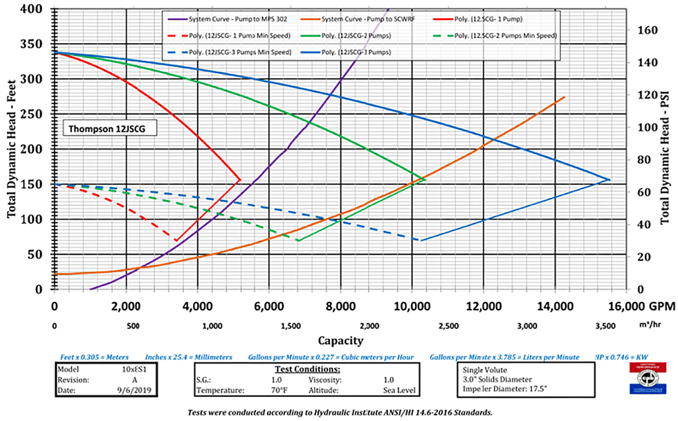
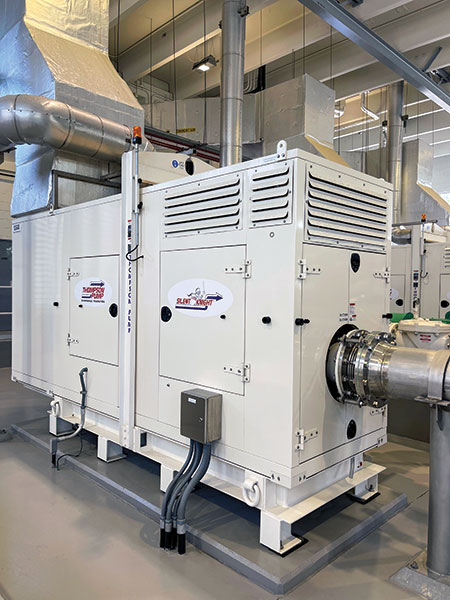
The station was designed with three electric-driven chopper pumps as the primary pumps during normal day-to-day operation, one 500 kilowatt (KW) standby generator in the event of a power failure and three 12-inch, diesel-driven emergency bypass pumps. Since the standby generator will only provide auxiliary power to the station, the bypass pumps were critical to supplement changes in flow/pressure and prevent any potential overflows at the multiple upstream pump stations. All bypass pump models were recommended based on a total peak flow rate of 3,700 gallons per minute (gpm) per pump with up to 150 feet of total dynamic head moving 11,000 gpm total.
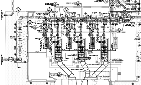
The suction side of the primary electric-driven pumps and the emergency bypass pumps were all designed to connect to a common, pressurized suction header pipe with automated gate valves that could redirect flow or isolate specific sections of the system when needed. The booster pump station was designed to pump to two different locations, either another booster pump station or the local wastewater reclamation facility much farther away. With changes to the discharge location, the system head curves for all pumps also changed. In other words, selecting the correct pump for each scenario was critical. Furthermore, the pumps needed to have the versatility to accommodate all possible conditions. All pumps would be automatically controlled by in-line pressure transducers, and, as a backup plan, all pumps could start, stop or change rotations per minute (rpm) with a command from the remote programmable logic controller (PLC).
All pumps were monitored and controlled through the municipal supervisory control and data acquisition (SCADA) system. The entire control sequence was the most important part of the design because six different pumps were being used, in parallel, and as needed.
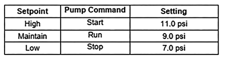
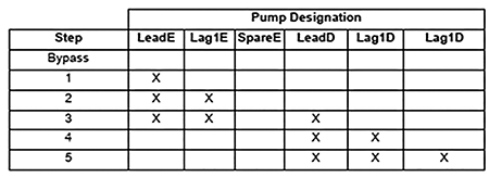
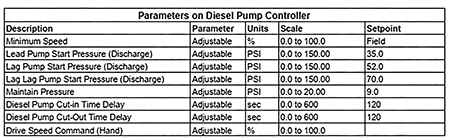
With independent pressure transducers assembled inside the influent suction pipeline, the pressure level would determine when all three electric pumps would start, stop or adjust rpm to maintain adequate pressure in the suction header. As pressure increased in the suction header, it would call the first emergency bypass pump (Lead Pump) to start and automatically maintain the pressure in the suction
header. If pressure dropped, the bypass pump would automatically reduce its rpm and shut down.
If the pressure continued to increase, the second bypass pump (Lag 1 Pump) would start, and both the bypass pumps would automatically adjust their rpm to maintain adequate pressure in the suction header. If pressure were to continue to increase in the suction header, the third bypass pump (Lag 2 Pump) would start, and all three pumps would automatically adjust their rpm to maintain adequate pressure in the suction header.
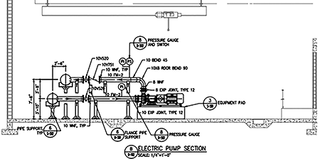
In addition to flow, pressure and the entire control sequence, this booster pump station would also be constructed inside a hurricane-rated 8,000 square-foot building with 25-foot ceilings, two 12-foot by 12-foot access doors and one five-ton overhead crane. All stainless steel, rigid suction piping, discharge piping, gate valves and check valves were 12 inches or greater in diameter, so the pump dimensions needed to be accurate in order for the construction of the project to stay on schedule. The overall size of the emergency bypass pumps created a challenge for the layout of all the equipment required, because they needed to be installed after the building and most of the piping was assembled.
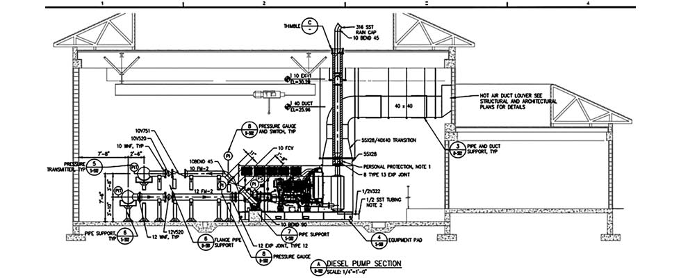
Since the bypass pumps are driven by a diesel engine, the engine exhaust and radiator airflow needed to be routed outside the building. The exhaust piping needed to be sized properly to prevent any excessive back pressure on the engine and needed to be properly secured with support pedestals and roof hangers, as it penetrated the roof of the building. Proper airflow was also required to maintain the proper operating temperature, so additional engine ductwork was constructed to connect the ambient air outside the building to the engine radiator.
This emergency backup generator and all three pumps also incorporated four 75-gallon auxiliary double-walled fuel tanks (day tanks) that connected to the one main 4,000-gallon diesel fuel storage tank located outside the building. All the day tanks were connected to a remote PLC to monitor the fuel levels, and each tank automatically refilled itself as needed. This design consideration assured the diesel fuel storage was enough to run the generator or the three pumps for a minimum period of 72 continuous hours, and less fuel was stored inside the building. In addition, all fuel storage methods could be removed, inspected or repaired as needed.
April 2021 was determined to be the date of substantial completion for the project. The new booster pump station was put online, and the existing station was decommissioned. The standby generator and all three emergency bypass pumps are exercised regularly and field preventative maintenance is performed as needed.
Over the course of the last 27 months, the station has been tested with massive rain events, tropical storms and the recent Category 4 Hurricane Ian making landfall just a few miles north of Naples, Florida. To date, zero sanitary sewer overflows associated with this new booster station have been reported.
