

There is constant pressure to reduce costs and reduce energy consumption. For applications such as liquid pipeline pumping, operations managers commonly use alternating current (AC) induction two-pole (3,600 rotations per minute [rpm] at 60 hertz [Hz]) motors. Selecting a stiff shaft motor suitable for variable frequency drive (VFD) duty facilitates energy cost savings across a wide power range and helps operations teams to meet their energy savings goals. To understand how, end users should consider a common application, shaft option differences, and how those differences combine with applications to deliver cost savings.
Common Application
A pipeline owner would like to be able to operate a 3,000-horsepower (hp) pump between 1,400 and 3,600 rpm. When using other motors, operators can traditionally only reduce the volume of the flow by applying valves and/or other flow dampening devices. These valves and dampeners can waste energy. This can be compared to holding down an accelerator on a car and using the brake to control the speed.
Motors can operate on VFDs at different speeds to produce a variable flow without wasting brake energy. The VFD can be run at a lower power output and reduce the energy used to drive the entire system without having to reduce the flow using energy-wasting valves or dampeners.
.jpg)
Shaft Options
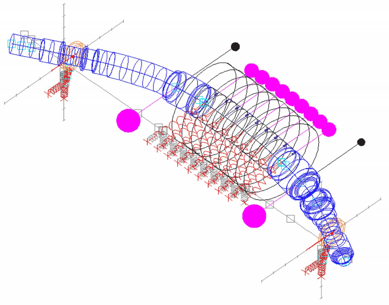
The two main motor shaft design options are stiff and flexible. All motor drive shafts will have a resonance frequency where the shaft will begin to bend during use and threaten the integrity of the motor. By traditional definition, resonance frequencies occur when the excitation of a material or structure aligns with its natural frequency to create amplification—sometimes uncontrolled. There may be multiple critical speeds in theory, but in practice, users are normally concerned only with the first critical speed.
Flexible shaft motors have the characteristic of at least one critical speed associated with a bending mode below the designed, base operating speed of the motor. Stiff shaft motors are designed with the first critical speed associated with a bending mode that would be above the designed operating speed of the motor.
Designing motors for lower power applications is simpler. Most motors below 800 hp will have a rotor with a stiff shaft design as standard. For large motors with high power requirements (above 8,000 hp), motor rotors will normally only be available as flexible shafts without moving to what is referred to as high speed motors. Therefore, for typical two-pole motors, stiff shaft or flexible shaft design becomes a critical motor characteristic between 800 and 8,000 hp for motors to be operated on a VFD.
When Each Option Becomes Optimal
When choosing between flexible and stiff shaft motor designs, an operations manager needs to consider the use case. Either stiff or flexible shaft motors can be used for constant speed, constant flow applications. For the case of flexible shaft motors, the non-VFD startup accelerates past the region where the shaft would have high vibration fairly quickly, such that the motor and driven equipment will not be endangered.
Flexible shafts may also be used with VFD motors, however, the VFD controller will need to be programmed to block out speed range(s) around the critical speed(s) to prevent damage to the motor and driven equipment due to high vibration.
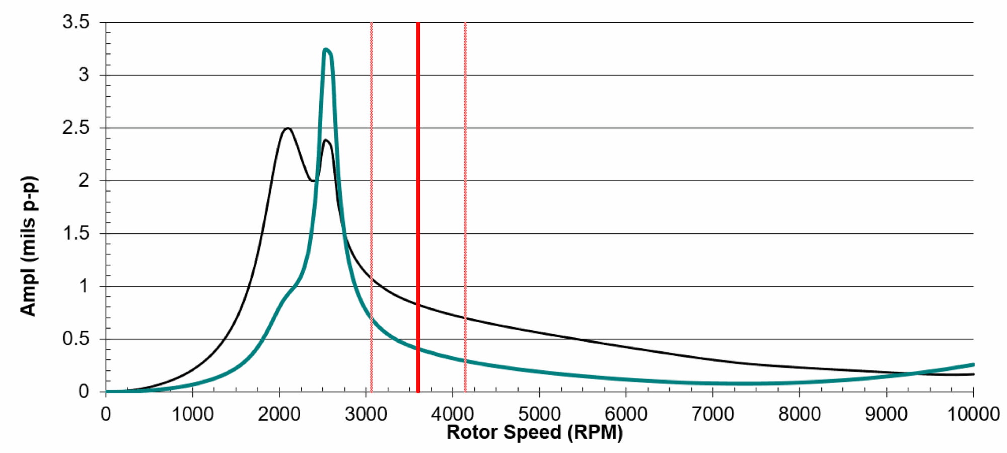
Image 4 illustrates the amplitude of the shaft displacement of a flexible shaft through a range of rpm. The critical first speed occurs at 2,520 rpm and can be seen as an increase in displacement from less than 0.5 mils (mil = 0.001 inch) p-p to more than 2 mils p-p in the X-dimension (black line) and more than 3 mils p-p in the Y-dimension (blue line). The red line represents 60 Hz operating speed of the motor. The dotted red lines illustrate the 15% separation margin required by the American Petroleum Institute (API) Specification 541 between the critical first speed and the operating speed. This particular shaft profile would more typically be found in a motor designed for continuous speed applications.
Stiff shafts work for VFD applications. Using a shaft with the first critical speed past the range of operation allows a VFD motor to provide the required speed and operational capacity for a full range up to operating speed without the requirement for blocked out speed range. Operators and systems designers should be careful to understand their VFD operational requirements and to specify stiff shaft motors when they desire broad speed range capability.
Rotor dynamics can be quite complex and will be affected by many other variables besides the staff stiffness and rpm. The motor enclosure—weather protected Type II (WPII), totally enclosed water to air-cooled (TEWAC), totally enclosed air to air-cooled (TEAAC), totally enclosed fan-cooled (TEFC)—and the motor voltage rating will also combine to determine when a motor standard design is stiff or flexible. When considering a new motor for a VFD pump application, it is recommended that the motor manufacturer be contacted to ensure that a motor design is a stiff shaft instead of a flexible shaft design.
The design of two-pole motors has progressed with ratings up to 8,000 hp with a stiff shaft rotor design, expanding the power range and the number of applications that can benefit from the potential energy savings.
