

A submersible pumping system consists of a multistage centrifugal pump coupled to a submersible motor that has been designed for installation in a narrow well. Submersible motors are available in various construction designs—including encapsulated and rewindable—and their horsepower ranges and physical size vary. So, what is right for each user’s application needs? This article takes a closer look at what users should consider when selecting a submersible motor.
Motor Pairing Options
When it comes to selecting an electrical submersible motor, not all manufacturers will use the same design. There are several technologies to choose from, including induction and permanent magnet (PM).
Induction motors have often been considered the workhorse of submersible systems. They typically feature a squirrel-cage design as there are no electrical connections between the rotor and stator that need to be kept watertight. Additionally, induction motors of this type can be repeatedly produced to ensure high quality and low cost, making them an accessible solution for pumping system owners and operators.
Since the motor is induction-driven, the rotor turns at less than synchronous speed, which is why this motor type is often referred to as an asynchronous motor. This speed differential is defined as slip. Due to the rotor slip and the shape of the motor’s torque-speed characteristic curve, the motor has stable operating characteristics, even under short overload and peak-load conditions that make it an ideal driver. When properly selected, the squirrel-cage induction motor can easily meet the load demands of a centrifugal pump.
PM motors are growing in popularity in submersible applications. Unlike an induction motor where the internal rotor is an electromagnet and becomes energized by the system’s power supply, PM rotors are always magnetized due to the raw material selection. These internal magnetic rotors make them more efficient, especially at reduced speeds and partial loads.
The inclusion of the rare earth magnet rotor removes the slip factor seen in an induction-style motor. This creates the opportunity to achieve full synchronous rotational speeds in cases where that provides an operational benefit. Another way to view this is that lower input power is required for an equivalent output power produced by an induction design motor—saving on operational costs every time the motor runs.
Installation
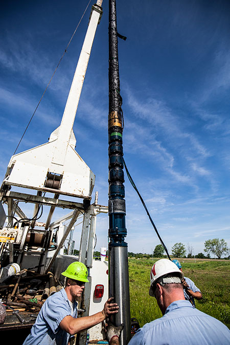
Submersibles are normally classified to indicate the smallest well-casing diameter to accommodate the pump: typically, from 4 inches to 12 inches. These often include power ratings as low as one-third horsepower (hp) up to 250 hp.
Because drilling and well construction costs increase dramatically with borehole diameter, submersible pumps and motors are characterized by their slender construction. During installation, the device should be set as close as possible to the running amps, with a maximum setting at 90% of nominal motor current and a trip time less than 10 seconds at 500% nominal current. It should also protect against single phasing and voltage variation.
Maintenance Best Practices
For daily startup, variable frequency drives (VFDs) improve system life with a soft-start feature. This controls the electrical current and voltage as it is provided to the motor, and it reduces the system stress associated with each startup. This “easing-in” to running at full speed minimizes pressure on the entire system. It also helps reduce the heat output on the motor, a big help in prolonging motor life.
When a motor fails, it is important to quickly determine the cause. If the failure is related to misapplication or improper installation, all installation deficiencies must be corrected before another motor is installed. Both motor types are repairable and spare parts are often readily available. The modular concept divides the motor into its main parts: stator, rotor, upper and lower end bell, seals and bearings.
The reliable and proven mechanical parts, end bells, seals and bearings are interchangeable for both induction and PM designs. When the failure mode is that of a failed stator, the encapsulated motor’s stator may be replaced or the rewindable motor may be rewound.
An encapsulated motor can be repaired quickly with a factory original stator. This results in no change in motor performance since each stator is wound using the same raw materials, automated winding lines and manufacturing processes.
The rewindable motor is easy to rewind in the field. The ends of the 18-slot stator are open to allow removal, reinstallation and forming of the winding coils. The motors are wound with polyvinyl chloride (PVC) wire, which is widely available, and the winding data is published. It is important to repair the motor under factory specifications for materials and winding data. Failure to do so will result in altered motor performance.
Repair kits that contain pre-wound coils, slot insulation and cable-splicing materials are available from the factory should the user or the repair shop prefer to use factory components.
Additional Application Considerations
In addition to how the motor will be used, consider the environmental conditions the motor will experience. For example:
Is there adequate power supply?
The power supply must provide adequate voltage and current balance to prevent excessive heating in the motor. Properly grounded surge protection should be installed to protect against high voltage spikes. In addition, the supply cables must be large enough to allow adequate voltage to reach the motor terminals. Motors are designed for a wide voltage variation range. The current imbalances must not exceed 5% from line to line.
Can proper motor temperature be maintained?
Some submersible motors are designed to operate in water at higher temperatures or lower flow conditions. For example, some motors can operate with nominal load at a maximum water temperature of up to 86 F (30 C). Other motors are specifically engineered to operate in much higher water temperatures—some even up to 194 F (90 C).
Choosing the best motor to power a submersible pump is critical to a system’s success. The motor’s long-term performance—and the performance of the pumping system—relies heavily on having the right configuration for the user’s site and user needs.
The Submersible Wastewater Pump Association’s (SWPA) purpose is to enhance the global wastewater environment by informing, educating and providing leadership in the design, procurement and operation of submersible wastewater pumping systems. For more information, visit swpa.org.
