
Misunderstood pump element serves to minimize mixing loss
It is a common misconception in the U.S. pump industry that the function of the volute is that of a diffuser: to convert velocity into pressure. I have recently read and heard statements to this effect by centrifugal pump authorities. Igor Karassik [3] said that the “velocity is converted into pressure energy by means of a volute.” Walter K. Jekat [4] said that the “most popular…diffusion system…for centrifugal pumps is the volute.” The McGraw-Hill scientific dictionary [5] states that a volute is “a spiral casing for a centrifugal pump…designed so that speed will be converted to pressure.”
Function at BEP
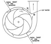 | 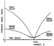 |
Figure 1. A single-volute casing maintains a constant velocity and uniform pressure around the impeller only at BEP. |
Figure 2. Hydraulic radial thrust for volute casings.
It is understandable that such a concept has been adopted because the volute has an increasing flow area as it wraps around the impeller, similar to a diffuser, but it is not the purpose of the volute to be a diffuser. Its function—when the pump is operating at the best efficiency point (BEP)—is to keep the velocity constant around the impeller so that mixing losses are minimized. To achieve that function, the area increases so as to accept the additional flow exiting the impeller, which exits the impeller all around the outside diameter (OD)—360 degrees. The pressure surrounding the impeller is uniform, resulting in zero hydraulic radial thrust on the impeller.
Performance with Restricted Flow
When the flow from the pump is restricted, forcing the pump to operate at a reduced capacity, the flow from the impeller is reduced, and the volute does act as a diffuser, creating an increasing pressure from the cutwater all the way around to the casing throat. The maximum pressure rise occurs at shut-off (zero flow). As shown in Figure 1, this rise in pressure around the impeller creates a radial thrust on the impeller that pushes the impeller in a direction approximately 90 degrees downstream from the cutwater. As shown in Figure 2, the maximum thrust occurs at shut-off.
Performance with Excess Capacity
When the pump is allowed to operate at a capacity that exceeds the BEP, the result is just the opposite. The velocity around the impeller increases, from the cutwater to the throat, causing a drop in pressure. This results in a radial thrust that pushes the impeller in the opposite direction, approximately 270 degrees downstream from the cutwater, as shown in Figures 1 and 2. A.J. Stepanoff [1] got it right. He talks about a constant-velocity volute.
References
- Stepanoff, A. J., Centrifugal and Axial Flow Pumps, John Wiley & Sons, New York, 1948.
- Stepanoff, A. J., Pumps and Blowers – Two-Phase Flow, John Wiley & Sons, New York, 1965.
- Karassik, Igor J., “Centrifugal Pump Construction”, Section 2.2 of the first edition of the Pump Handbook, edited by Karassik, Krutzsch, and Fraser, McGraw-Hill Book Co., New York, 1976.
- Jekat, Walter K., “Centrifugal Pump Theory”, Section 2.1 of the first edition of the Pump Handbook, edited by Karassik, Krutzsch, and Fraser, McGraw-Hill Book Co., New York, 1976.
- Dictionary of Scientific and Technical Terms, Fourth Edition, McGraw-Hill Book Co., New York, 1989.
Pumps & Systems, January 2012
