

Mechanical seals are precision, dynamic devices that are used to seal process fluids from the environment and have been utilized by pump and other rotating equipment users for approximately 100 years. Today, the same four basic components and fundamental principles apply to all mechanical seals, but this technology has evolved over the past 100 years, so seal users have a variety of choices to meet their specific technical, commercial and reliability needs.
The purpose of this series is to give users a foundational background in the technology of mechanical seals from
which they can start to make informed decisions regarding the different
types and configurations available for today’s applications. First, however, we need to understand just how a mechanical seal works.
To understand how a mechanical seal works, we need to understand the basic components that make up the anatomy of any mechanical seal. Image 1 shows the cross section of two different types of mechanical seals, which show the same basic four components.
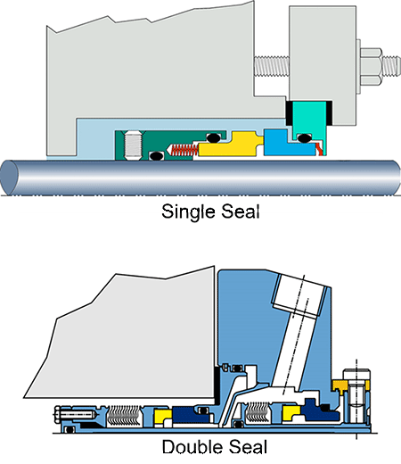
IMAGE 1: The cross section of two different
types of mechanical seals, showing the same
basic four components (Images courtesy of
A.W. Chesterton Company)
The components of a mechanical seal include the following:
1. Seal Face Pair
The seal face pair creates the primary sealing interface, which provides rotational, dynamic sealing within the mechanical seal. Depending on the seal configuration, there will be either one face pair known as a single seal or two face pairs, which are known as a double seal. Some mechanical seals may have more face pairs, but these seals are custom designed for a specific application. The face pairs are made from a variety of carbon/graphite materials, as well as hard ceramic materials such as silicon carbide, tungsten carbide or alumina ceramic. Each of these materials offers different operating characteristics and capabilities to the mechanical seal.
2. Secondary Seals
Each mechanical seal will also have a variety of secondary seals, which are used to prevent leakage from various other interfaces within the mechanical seal. Most of these secondary seals are static in nature, but one is dynamic to allow the
seal faces to dynamically track each other when the equipment is in operation. If the seal face pair loses dynamic tracking, there will be excessive leakage from the mechanical seal.
Secondary seals come in a variety of different elastomeric materials in various forms, including O-rings, gaskets, wedges, boots or metal/elastomer bellows, as shown in Image 2.
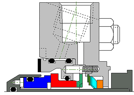
IMAGE 2: Mechanical seal showing the various secondary seals, including O-rings and a gasket
3. Springs & Loading Mechanisms
The third major component of any mechanical seal are the springs or other loading mechanisms used to maintain face contact during static, non-rotational times and dynamic tracking during operation.
These springs and loading mechanisms can take the form of a large diameter single spring, multiple smaller diameter springs, leaf springs, wave springs or a metal or elastomeric bellows. The proper function of these loading mechanisms is critical to the leakage control of any mechanical seal. Image 4 shows some of the different loading mechanisms that can be used.
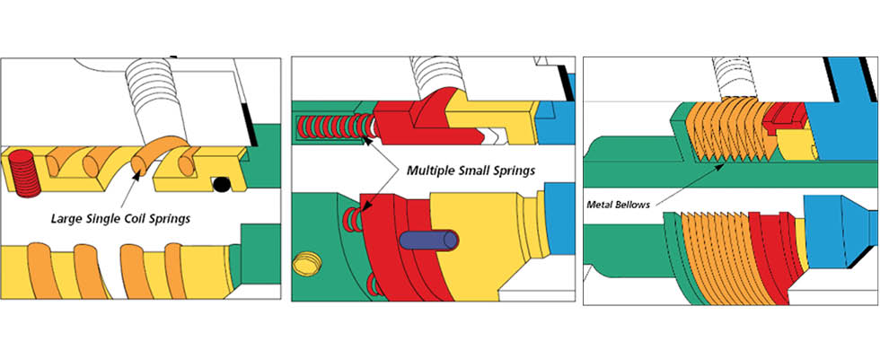
IMAGE 4: Different types of loading mechanisms
4. Structural Components & Hardware
The last major components are the metal parts and hardware. These include the gland, sleeve, lock ring and the various pieces of hardware used in the mechanical seal.
Glands are typically supplied in a stainless alloy, but depending on the application requirements, several other alloys may be used, including alloy 20, duplex or super duplex, titanium, Hastelloy or Inconel. The hardware and fasteners include pins, lugs and screws, which are used to assemble and hold the seals components in place.
5. Setting Clips
The final component is the seal’s centering device or setting clips. These devices have two critical functions. First, they aid in the shipping of the mechanical seal to assure there is no internal movement that could damage the seal faces or other components. Secondly, and just as importantly, these centering devices set the intended spring compression to assure optimal seal operation and reliability. Image 6 shows the cross section of a typical cartridge seal’s structural components and hardware.
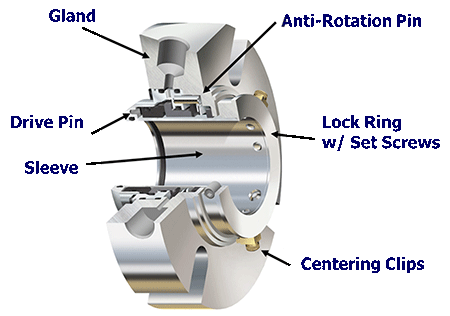
IMAGE 6: Cross section of a typical cartridge seal’s structural components and hardware
The second area that all mechanical seals share are the configurations offered by the various manufacturers. The seal configuration offered is dependent on the requirements of the application. There are both general configurations offered
as well as application specific configurations to suit specific industry needs. Most seal manufacturers offer a variety of these configurations.
Component seals
A component seal is one where the rotary component and stationary component are two separate units that must be assembled during pump assembly. This configuration dates to the first mechanical seals offered to the market. They are simple and low cost, but they typically do not have the same performance capabilities found in other configurations.
Cartridge seals
Cartridge seals are built on the concept that the seal components are assembled into a cartridge unit. This configuration offers greater reliability, as it dramatically simplifies the installation process, as well as reduces the time frame required. Cartridge seals are offered in single, double or tandem configurations to suit the specific application requirements
and offer higher operating capabilities. Image 7 shows the various cartridge configurations available.
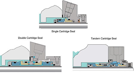
IMAGE 7: Various cartridge configurations
Split mechanical seals
Split mechanical seals have been available off the shelf for the past 40 years. As the name implies, they are fully split, which allows for installation and repair without the need for costly removal of rotating equipment when excessive seal leakage occurs. This technology has seen several evolutions over the past 40 years, which have resulted in improvements in the ease of installation as well as sealability, approaching higher performance cartridge seals. Image 11 shows the typical configuration.
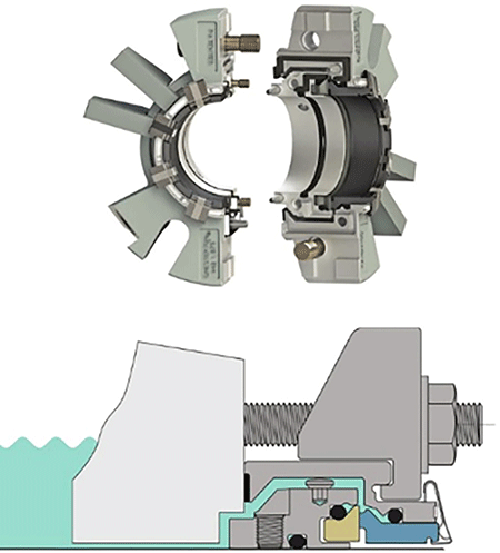
IMAGE 11: Typical configuration of a split mechanical seal
Equipment & Application Specific Designs
Finally, there are many equipment or application specific seal designs that offer an optimized solution for challenging application. For example, slurry seal technology offers seal faces designed to limit the potential of pulling particulates into the sealing interface and are designed to be more robust than standard seals to handle the motion and shocks many slurry pump applications experience. Image 8 shows a cross section of a slurry seal design.
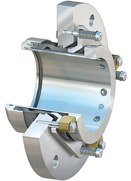
IMAGE 8: Cross section of a slurry pump
seal design
Gas seal technology is another adaptation for specific applications where an inert gas barrier is needed due to the application requirements. The seals are based on compressor gas seal technologies but are adapted specifically to pumps. This seal design does not rely on a liquid to provide the seal with its required lubrication and cooling, instead an inert clean/dry barrier gas such as nitrogen is used. One of the seal faces in a gas seal design will have face features that help to separate the faces while in operation, known as hydrodynamic lift. Some designs also include a degree of hydrostatic lift, which means the faces begin to separate before seal rotation starts. Image 9 shows a cross section of a gas seal design specifically for pumps.
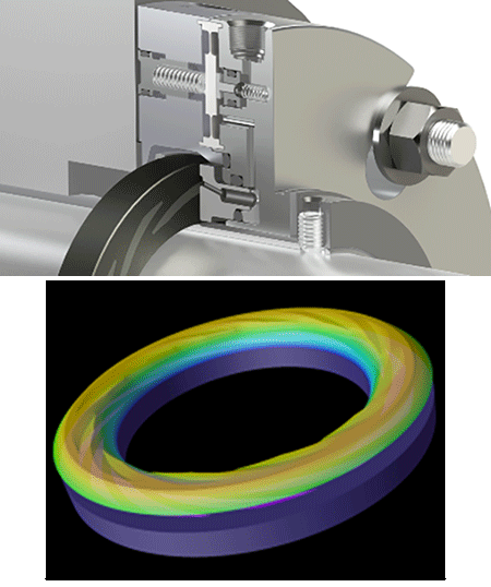
IMAGE 9: Cross section of a gas seal design
for pumps
Mixer seals are a special category of equipment/application specific design that incorporate several different capabilities to meet the needs of the specific mixer/reactor/agitator application. These seals can include:
- extra motion capabilities
- dry running capabilities
- debris wells
- integral bearings for greater stabilization
- hydrostatic lift capabilities for slow shaft speed applications
- design for glass-lined vessels that cannot accept a standard metallic alloy due to the nature of the fluid sealed
Image 10 shows some of these features used in various mixer seal designs.
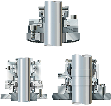
IMAGE 10: Features used in various mixer
seal designs
Today, plants have a variety of designs and configurations to choose from. Determining which to use can be difficult at times. This is where a trained sealing device specialist can help in the seal selection process. In next month’s edition, we will explore how a mechanical seal “seals” and what features to look for based on the application’s specific requirements.
