

For gaskets to be effective in their application, the designer of a bolted flanged joint (BFJ) must select a gasket with the appropriate mechanical properties for the application. In any case, the mechanical behavior of the gasket must be known and well understood. Industry testing standards exist to detail these mechanical behavior characteristics at ambient temperature and elevated temperatures that are representative of the temperature conditions the gasket may expect to encounter in service.
However, no testing standard exists for determining these characteristics at temperatures below ambient conditions, which are common application temperatures for gaskets. In this article, a comparison of mechanical properties for one gasket configuration from subambient temperatures to elevated temperatures is made.
Industrial gaskets are called on to reliably seal the internal media across a broad spectrum of pressure and temperature conditions. To have a high degree of confidence in the gasket’s ability to seal the media, the BFJ designer considers these conditions and endeavors to find a gasket that can withstand them. To assess a gasket’s viability, the designer reviews the mechanical characteristics of the gasket, often as determined by industry testing standards.
Different testing standards from different standardization bodies (e.g., ASTM International and the European Committee for Standardization [CEN]) provide different types of tests to deliver these critical values. These standardized tests can be performed at ambient temperature or elevated temperatures, but an obvious gap in this information is the absence of gasket characteristics at subambient temperatures.
At the time of this writing, no industry testing standard exists with provisions for determining gasket properties at subambient temperatures. This information gap puts the designer in a predicament where they are required to use existing data (data at ambient temperature) as a proxy for what they might reasonably expect the behavior to be at subambient temperatures. Or worse yet, the designer may estimate the characteristics.
Examining Two Gasket Characteristics: EG & PQR
As a small sample study, let’s take a closer look at how these mechanical behaviors at subambient temperatures
can vary from the behaviors at ambient and elevated temperatures for one particular gasket in two specific tests.
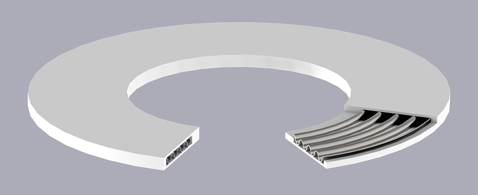
The gasket in question being a polytetrafluoroethylene (PTFE)-enveloped gasket with a corrugated steel core with a DN40/PN40 geometry and nominal thickness of 3 millimeters (mm), a generic representation of which can be
seen in Image 2. The tests are adapted from EN13555: 2014 edition, with the caveat that the tests deviate from the standard in the cases where they are performed at subambient temperatures:
- elastic modulus (EG) test
- creep-relaxation factor (PQR) test
The value EG is the unloading modulus of the gasket expressed in megapascal (MPa), and is determined from the thickness recovery of the gasket from an initial stress during a 66.6% stress reduction. This value is calculated over a range of surface stresses in intervals of 10 and 20 MPa: 20, 30, 40, 50, 60, 80, and so on. This procedure thus provides a data set of EG values across a broad range of initial gasket stresses. The test can be performed at any temperature to provide the relevant EG values for a given application.
The value PQR is the relaxation factor of the gasket expressed as a value between 0 and 1, and it represents the stress-loss effects of the creeping of the gasket material from long-term surface stress exposure. This value is calculated as a ratio of the stress at the end of the stress exposure (for a period of four hours) versus the stress prior to temperature exposure. In essence, it shows how much surface stress is lost on the gasket as a function of the overall stiffness of the joint, the initial stress imposed and the application temperature.
Taken together, the values EG and PQR provide a robust set of information on how a gasket material responds to different loading situations and temperature exposures. The above descriptions of each value serve only to lend insight and meaning to the statements and figures presented below. The EN13555 standard should be consulted for more detailed information on these values and testing procedures.
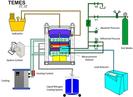
Numerous facilities have the equipment necessary to perform these tests according to the standard at ambient and elevated temperatures. But to reach subambient temperatures an additional cooling system that is capable of reaching the desired subambient temperatures must be integrated into the testing device. See a common schematic of this type of equipment in Image 1, which is an automated servo-hydraulic press outfitted with a liquid nitrogen cooling system.
A Comparison of EG Values
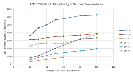
The elastic modulus test was performed on the chosen gasket described above in five different tests, on five individual samples at five different temperatures: -150 C, -100 C, -50 C, 25 C, 100 C and 250 C. The test sequence was executed up to a maximum surface stress of 100 MPa, except in the case of the test at 250 C, where the gasket was destroyed beyond a surface stress of 60 MPa. The differences in the values of EG for each corresponding temperature and surface stress can be seen in Image 3. As seen in the image, there is a discernible difference in the EG values consistent with the variations of the test temperatures.
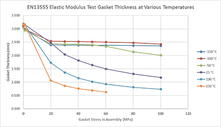
The trend in the behavior, at least for this gasket and these parameters, is clear: higher temperatures lead to a softer gasket with lower EG values, while progressively cooler temperatures result in progressively stiffer behavior with progressively higher EG values. The material’s reaction to different temperatures can also be visualized in terms of the gasket’s overall thickness over the same measuring points from the above tests (Image 4).
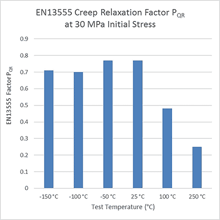
A Comparison of PQR Values
In the same way as the elastic modulus test, the PQR test was performed on the chosen gasket described above in five different tests, on five individual samples at five different temperatures: -150 °C, -100 C, -50 C, 25 C, 100 C and 250 C. The initial gasket stress for the purposes of determining PQR in this test was set to 30 MPa. The differences in the values of PQR for each corresponding temperature can be seen in Image 5. There is clearly a discernible difference in the EG values consistent with the variations of the test temperatures.
Unlike the EG values, the relationship of PQR to temperature is much less discernible for ambient temperatures and below. The greatest break in the trend occurs when the temperature is raised above ambient.
The differences in the material’s mechanical properties over the broad temperature range presented are more than just interesting facts. The differences have real consequences regarding the designer’s approach in determining bolt loads for installation and the subsequent performance of the material in the application. This small sample set proves, at least for this particular gasket, that using the “closest available proxy” (in this case, gasket characteristic data at ambient temperatures), is not sufficient when designing BFJs for subambient temperature applications. For applications at these low temperatures, it is in the designer’s best interest to seek out the chosen gasket’s true mechanical properties at the application conditions for designing and implementing a high-performing BFJ.
We invite your suggestions for article topics as well as questions on sealing issues so we can better respond to the needs of the industry. Please direct your suggestions and questions to sealingsensequestions@fluidsealing.com.
