
First of a Two-Part Series
04/10/2014
See part two here.
Gasket blowout is the most catastrophic of gasket failures. It usually occurs with no discernible warning and causes a sudden and significant release of internal pressure, usually accompanied with loud popping sound or whistle. Depending on the process being contained and/or the amount of stored energy at the time, the result can be fatal.
Part One of this two-part Sealing Sense series brings attention to the balance of forces present at the potential moment of gasket blowout and provides guidance on how to protect against this type of gasket failure. Equations are provided to assist with evaluating these forces and results are presented to show that to protect against blowout, clamping force can be significantly more important than gasket tensile strength.
Blowout Forces
For the purpose of this article, Figure 1 identifies the general condition of potential blowout. It shows an axial “cut” across the thickness of the gasket and the three general forces affecting blowout. Equation 1 provides the force balance in the radial direction. The potential condition of blowout is taken when the sum of these forces is equally balanced. That is, the forces holding the gasket in place and together is equal to the outward force trying to dislodge or damage it.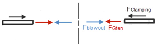 Figure 1. Forces on a gasket
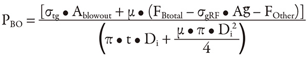 The added terms are defined as follows:
σtg = Tensile strength of gasket, 2,700 pound-force per square inch (lbf/in2)
Ablowout = 2 x gasket width x gasket thickness in compressed condition, in2
μ = Friction factor, gasket on flange face, 0.2
FBtotal = Total bolt load at original tightening torque, 32,914 pound force (lbf)
σgRF = Loss of gasket stress to time, temperature and loading history, 2,050 lbf/in2
Ag = Axial area of gasket, 5.84 in2
Di = Inner diameter of gasket, 2.38 inches
t = Thickness of gasket in compressed condition (0.0625 inch)
FOther = as above, 10,000 lbf
PBO = Blowout pressure, lbf/in2
The added terms are defined as follows:
σtg = Tensile strength of gasket, 2,700 pound-force per square inch (lbf/in2)
Ablowout = 2 x gasket width x gasket thickness in compressed condition, in2
μ = Friction factor, gasket on flange face, 0.2
FBtotal = Total bolt load at original tightening torque, 32,914 pound force (lbf)
σgRF = Loss of gasket stress to time, temperature and loading history, 2,050 lbf/in2
Ag = Axial area of gasket, 5.84 in2
Di = Inner diameter of gasket, 2.38 inches
t = Thickness of gasket in compressed condition (0.0625 inch)
FOther = as above, 10,000 lbf
PBO = Blowout pressure, lbf/in2
Analysis of Blowout Factors
A way to trial different values to inspect their potential effect on PBO is available. It will be used to test the general belief that gasket tensile strength is always a major factor in preventing gasket blowout. To investigate, two series of calculations are evaluated to the resulting value of PBO. The first series is performed by holding all values fixed, except σtg. Its value is progressively reduced in 5 percent increments. In the second series, all values are held fixed except, FOther. This shows the potential effect of an axial piping load or axial flange misalignment that tends to separate the flanges. Its value is progressively increased in 5 percent increments. The results are plotted in Figure 2.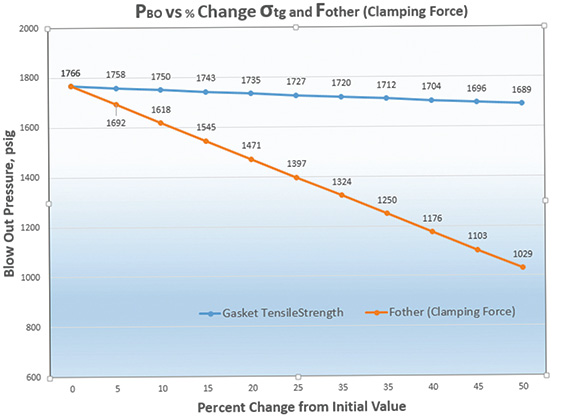 Figure 2. Effect of piping load and gasket tensile strength on blowout pressure