
The supply of oxygen to four aeration tanks is now handled by five centrally controlled turbocompressors.
Sulzer Pumps
10/07/2016
.jpg) Image 1. The diffusers in this water treatment basin split air into tiny bubbles. (Images and graphic courtesy of Sulzer)
Image 1. The diffusers in this water treatment basin split air into tiny bubbles. (Images and graphic courtesy of Sulzer)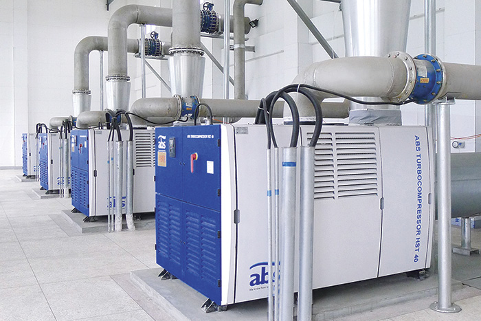 Image 2. These turbocompressors are used in biological sewage treatment to provide air flow to the diffusers in the water treatment basin.
 High-Speed Technology
The chosen turbocompressors are electric-motor-driven, low-pressure centrifugal air compressors. The impeller of the radial compressor, the electric motor and the cooling fan are integrated into one common shaft, which runs at a high speed. A frequency converter generates the required high supply frequency, and the bearing challenge is solved by using contactless active magnetic bearings (AMB). In addition to low friction losses, AMB allows for a totally oil-free design. The high-speed unit of the compressor is a highly integrated device. Despite design challenges such as high mechanical stresses, rotor dynamics, cooling and efficiency optimization, the high-speed unit provides excellent efficiency in a wide operating range and with sufficient margins to all technical limits, such as stresses, critical speed and maximum temperatures. Extensive experience and powerful modeling tools, especially finite element modeling, were required to meet the design goals.Active Magnetic Bearings
In an AMB, the rotating part levitates using actively controlled electromagnets. Even though the basic operating principle is straightforward and the AMB system is simple from the end-user viewpoint, the system is technically complex. In a typical application, radial actuators consisting of four horseshoe electromagnets are at both ends of the machine. In addition, two axial magnets typically keep the rotor in place axially. The control system needs to know the rotor position, so five position measurements are needed: two radial directions at both ends and the axial direction. Often, the axial direction is measured from both ends of the machine so the relative thermal expansion between the rotor and the stator can be monitored. Important features include the backup battery system and the touchdown bearing. The backup battery will levitate the rotor in case of a power outage. The function of the touchdown bearing is to ensure safe stopping of the machine in case of a rare AMB failure. An AMB basically can be controlled by conventional proportional-integral-derivative (PID) regulators. In demanding industrial applications, however, a higher-order, multi-input, multi-output control scheme is often needed. So-called force rejection control is also a necessary feature. Force rejection control eliminates the rotation-synchronous bearing force component caused by rotor unbalance. Consequently, during normal operation, the observed vibrations in the stator side are very low. AMB with force rejection control also tolerates a high level of rotor unbalance, which improves the reliability of the system. To levitate the rotor, the magnetic bearing controller (MBC) measures the rotor positions and makes control decisions 10,000 times per second. The MBC also monitors about 100 different variables, including whirling orbits, thermal expansion, static loads, coil currents, coil condition, temperatures and internal voltages. The AMB is not only a bearing, but also an extensive condition-monitoring system. It reports deviations from normal conditions to the compressor control unit, which shows alarm messages to the end user on the graphical screen.Development of Motor & Control System
The compressor uses two types of high-speed motors: either copper-coated induction motors or permanent-magnet (PM) motors. Compared with a copper-coated induction motor, a PM motor has less electromagnetic loss, which reduces the power needed for cooling. Its smaller size reduces the air friction, so the difference in total efficiency is larger than the difference in electromagnetic efficiency only.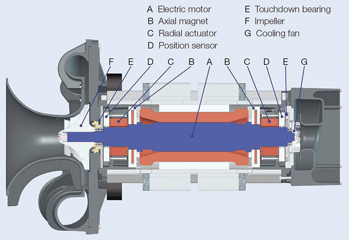 Figure 1. A cross section of a high-speed compressor unit
System Success
The new turbocompressors, aeration units and optimized controls have caused the specific energy consumption of the Sögel plant to drop by more than 50 percent in the past six years. More than 80 percent of this reduction is the result of the installed turbocompressors.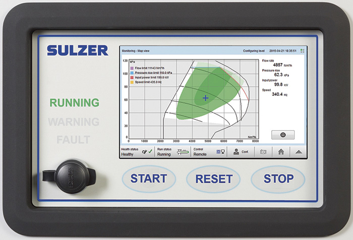 Figure 2. The user interface depicts the operating range of the compressor, the limits and the current operating point.