
In outdoor pump installations, the effects of a hot climate and exposure to the sun should not be taken lightly.
01/21/2015
Climate has an often ignored impact on sealing systems. Damage from harsh weather conditions, such as intermittent storms or humidity, can be effectively managed. But daily exposure to the outdoors, especially where extreme temperatures are the norm, can wreak havoc on seals.
Preventing Leaks with Pressure
Dual seals, Arrangement 3, as specified in American Petroleum Institute (API) 682, form a system where two seals prevent process fluid from escaping into the environment. The cavity between the two seals is maintained at a pressure that is higher than the process pressure in the seal chamber. The difference in pressure ensures that any leaks will be of the barrier fluid into the process or atmosphere and that the process will always be contained. This arrangement is also used where the process fluid has insufficient lubricating properties or is loaded with solids that would damage seal faces. In this case, the barrier, not the process, fluid is sealed. A schematic of the arrangement is shown in Figure 1.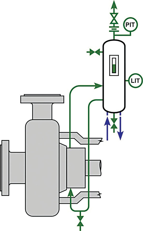
 Figure 1. The schematic above shows a dual-seal system according to Plan 53A. (Graphics courtesy of the author)
Hotter Climates, More Pressure
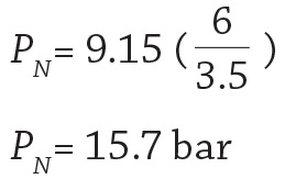
In a pressurized dual-seal system, the barrier pressure should always be above the process pressure. While this pressure differential is essential to the success of the seal, rarely is the seal cavity pressure measured with a gauge. Instead, end users estimate the pressure depending on the design and construction of the pump, operating conditions and piping plans that modify the seal chamber pressure. The maximum pressure may easily be estimated at 7 bar (0.7 MPa, 101.5 psig) for what might be a normal seal cavity gauge pressure of 5 bar (0.5 MPa, 72.5 psi). The barrier fluid pressure would then be set at least one atmosphere higher than the maximum seal cavity pressure, or 8 bar (0.8 MPa, 116 psig). This pressure level would have to be maintained at all times, including at the minimum ambient temperature. Ambient temperature changes cause pressure variations in the barrier-fluid tank used to circulate the barrier fluid for a dual seal. The system must be set so that the desired pressure is maintained at the lowest ambient temperature. The result is that at the maximum ambient temperature, the system will end up at a higher pressure. In one example, the minimum ambient temperature is 5 degrees Celsius, and the maximum ambient temperature is 45 C. Equation 1 calculates the change in pressure.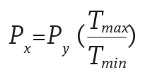
Equation 1
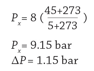
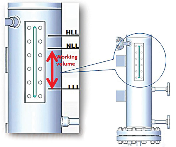 Figure 2. The fluid level fluctuates between low (LLL), normal (NLL)and high (HLL).
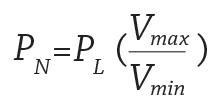
Equation 2
Other Sources of Heat
The seal also generates heat during operation.The heat is transferred to the tank and dissipated into the environment. An equilibrium above the ambient temperature will result. For this example, a typical increase in temperature is 25 C above ambient. At the maximum ambient temperature conditions, this increase results in a barrier fluid temperature of 70 C. The change in pressure can be calculated using Equation 1, where 15.7 bar now serves as the pressure at the low temperature, or Py. The resulting pressure at the high ambient temperature is 16.9 bar (1.69 MPa, 246 psi).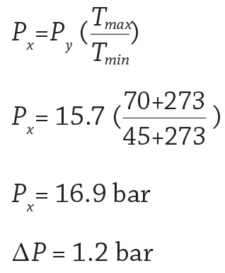
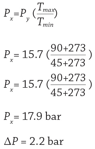
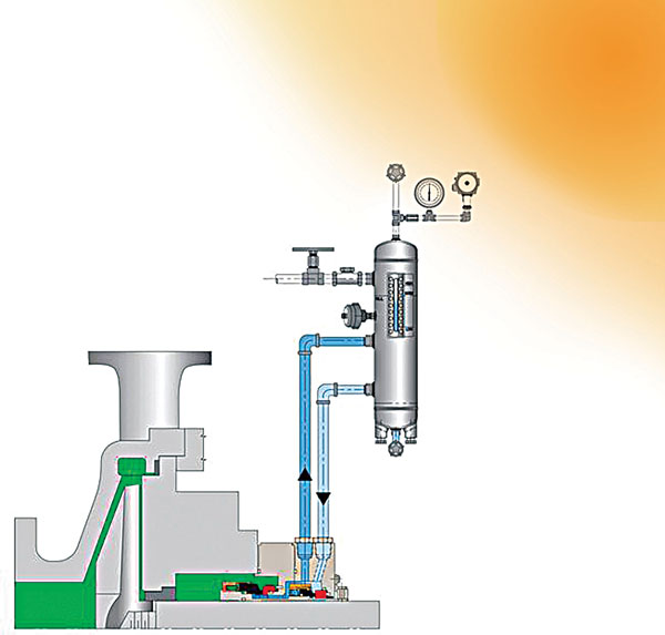 Figure 3. Prolonged exposure to solar radiation increases tank temperature and pressure.
Solving the Pressure Problem
For outdoor installations, the following tips can protect seal life against the dangers of rising pressure from high temperatures:- Install the tank somewhere with constant shade.
- Use the largest tank possible. Larger tanks reduce pressure variation for the same variation in barrier fluid volume.
- Check balance ratios and choose a seal designed for high barrier fluid pressure on the primary seal.
- Use a pressure regulator to maintain constant pressure. The regulator must allow venting to reduce pressure when the tank temperatures are too high. A regulator will not be the best option if process vapors mix with the barrier fluid.
